Command Syntax
2–10
TLS 216 Programmer Manual
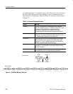
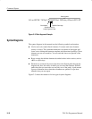
ALIas:DEFINE SETUp1",#231AUTOSet EXECute;:SELect:REF1 ON
Block Header
Specifies Number of
Length Digits that Follow
Specifies Data Length
Block Argument
Figure 2–2: Block Argument Example
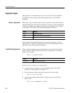
Syntax Diagrams
The syntax diagrams in this manual use the following symbols and notation:
H Circles and ovals contain literal elements. You must send most elements
exactly as shown. The command mnemonics are shown in both upper and
lower case to distinguish between complete and abbreviated spellings. These
elements are not case sensitive. You can omit the lower case portion of the
mnemonic.
H Boxes contain the defined elements described earlier in this section, such as
<NR3> or <QString>.
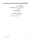
H Elements are connected by arrows that show the allowed paths through the
diagram and, thus, the orders in which you can send the elements. Parallel
paths show that you must take one and only one of the paths. A path around
a group of elements shows that those elements are optional. Loops show
elements that you can repeat.
Figure 2–3 shows the structure of a few typical syntax diagrams.


