Command Descriptions
TLS 216 Programmer Manual
2–269
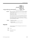
AUXiliary specifies the rear panel connector labeled AUX TRIGGER INPUT as
the clock source.
TRIGGER:DELAY:STATE:CLOCK AUXILIARY
designates the rear panel connector AUX TRIGGER INPUT as the clock
source.
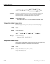
TRIGGER:DELAY:STATE:CLOCK?
might return CH1 as the clock source for the delayed state trigger.
TRIGger:DELay:STATE:INPut
Sets or queries the logic pattern input values for all 16 channels and the
Auxiliary Trigger input.
Trigger
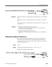
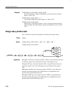
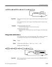
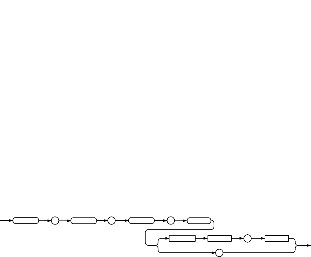
TRIGger:DELay:STATE:INPut <NR1>,<NR1> NOTE: 1-high,0-low
TRIGger:DELay:STATE:INPut?
TRIGger
:
DELay
STATE
:
:
<NR1> , <NR1>
INPut
?
<Space>
<NR1> is a value from 0 to 131071. The logic pattern input values of all channels
and the Auxiliary Trigger input are set according to this value. The parameter is
interpreted as a 17-bit binary number. Bits 1 through 16 are used to set the High
or Low values of channels 1 through 16. Bit 17 is used to set the High or Low
value of the Auxiliary Trigger input. A bit value of 1 for a channel indicates
High, a bit value of zero indicates a Low. NOTE: Bit values are ignored if the
matching bit in the second parameter is zero.
<NR1> is a value from 0 to 131071. The “Don’t Care” values of all channels and
the Auxiliary Input are set according to this value. The parameter is interpreted
as a 17-bit binary number. Bits 1 through 16 are used to set the “Don’t Care”
status of channels 1 through 16. Bit 17 sets the “Don’t Care” of the Auxiliary
Input. A bit value of zero will set the Boolean value to “Don’t Care” for that
channel, regardless of the first parameter bit value. A bit value of 1 for a channel
indicates the high or low value set by the previous parameter is used.
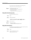
Examples
Group
Syntax
Arguments


