


Groundsmaster 4000--D/4010--D Hydraulic SystemPage 4 -- 59
Procedure for Lift/Lower Circuit Relief Pressure
Test
NOTE: Before attempting to check or adjust lift/lower
circuit relief pressure, make sure that counterbalance
pressure is correctly adjusted (see Counterbalance
Pressure Test in this section).
1. Make sure hydraulic oil is at normal operating tem-
perature by operating the machine under load for
approximately ten (10) minutes. Make sure the hydrau-
lic tank is full.
2. Park machine on a level surface with the cutting
decks lowered and off. Make sure engine is off and the
parking brake is applied.
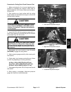
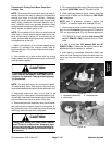
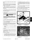
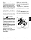
3. Remove controller cover t o gain access to lift/lower
manifold (Fig. 46).
CAUTION
Prevent personal injury and/or damage to equip-
ment. Read all WARNINGS, CAUTIONS and Pre-
cautions for Hydraulic Testing at the beginning
of this section.
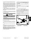
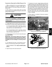
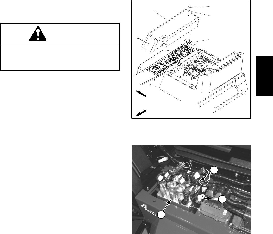
4. Connect a 5,000 PSI (345 bar) pressure gauge to
test port G1 on lift/lower manifold (Fig. 47).
5. Sit on the seat and start the engine. Move throttle to
high idle speed (2870 RPM).
6. While sitting on the seat, depress the rear of one of
the lift switches to fully raise the cutting deck. Momen-
tarily hold the switchwith thedeck fullyraised while look-
ing at the gauge.
GAUGE READING TO BE approximately 1600 PSI
(110 bar).
7. Release the lift switch,stoptheengineandrecord
test results.
8. Relief valve (RV1) is located on the top side of the lift/
lower manifold (Fig. 47). Adjustment of this valve can be
performed as follows:
NOTE: Do not remove the relief valve from the hydrau-
lic manifold for adjustment.
A. To increase pressure setting, remove cap on re-
lief valve and turn the adjustment socketon the valve
in a clockwise direction. A 1/8 turn on the socket will
make a measurable change in pressure setting.
B. To decrease pressure setting, remove cap on re-
lief valve and turn the adjustment socket on the valve
in a counterclockwise direction. A 1/8 turn on the
socket will make a measurable change in pressure
setting.
C. After relief valve adjustment, recheck pressure
setting and readjust as needed.
9. If relief valve adjustment does notchange relief pres-
sure, check for restriction in pump intake line, lift cylin-
der(s) internal leakage or gear pump damage.
10.When testing is completed, disconnect pressure
gauge from test port. Install controller cover.
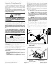
1. Controller cover
2. Screw (2 used)
3. Flat washer (2 used)
4. U--nut (2 used)
Figure 46
2
3
1
4
FRONT
RIGHT
1. Lift/lower manifold
2. Test port G1
3. Relief valve RV1
Figure 47
1
2
3
Hydraulic
System