Groundsmaster 4000--D/4010--DHydraulic System Page 4 -- 128
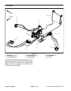
PTO Circuit
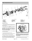
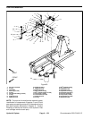
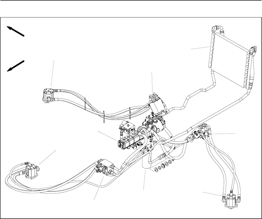
1. Gear pump
2. RH cutting deck motor
3. LH cutting deck motor
4. RH PTO manifold
5. Front cutting deck motor
6. LH PTO manifold
7. Front PTO manifold
8. Filter manifold
9. Oil cooler
Figure 98
FRONT
RIGHT
2
1
5
4
3
7
6
8
9
Figure 98 illustrates thecomponents that are used inthe
Groundsmaster 4000--D and 4010--D PTO circuit. Pro-
cedures for removal, installation and disassembly/as-
sembly of these components are provided on the
following pages of this section.


