


Groundsmaster 4000--D/4010--D Hydraulic SystemPage 4 -- 11
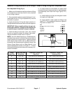
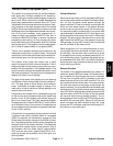
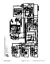
Traction Circuit: Low Speed (4WD)
The traction circuit piston pump is a variable displace-
ment pump that is directly coupled to the engine fly-
wheel. Pushing the traction pedal engages a hydraulic
servo valve which controls the variable displacement
piston pump swash plate to create a flow o f oil. This oil
is directed tothe front wheel andrear axle motors. Oper-
ating pressure on the high pressure side of the closed
traction circuit loop is determined by the amount of load
developed at the fixed displacement wheel and axlemo-
tors. As the load increases, circuit pressure can in-
crease to relief valve settings: 4000 PSI (274 bar) in
forward and 5000 PSI (343 bar) in reverse. If pressure
exceeds the relief setting, oil flows through the piston
pump relief valve to the low pressure side of the closed
loop traction circuit. The traction circuit provides opera-
tion in either Hi speed (2WD) or Low speed (4WD).
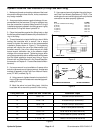
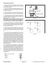
Traction circuit pressure (forward and reverse) can be
measured at test ports in hydraulic tubes. The forward
traction port is on the left side of the machine and the re-
verse traction port is on the right side of the machine.
The traction circuit pump and motors use a small
amount of hydraulic fluid for internal lubrication. Fluid is
designed to leak across traction pump and motor com-
ponents into the case drain. This leakage results in the
loss ofhydraulic fluid from the closed loop traction circuit
that must be replaced. The charge circuit is designed to
replace this traction circuit leakage.
The gear pump section that supplies oil to the steering
and lift/lower circuits also provides oil for the charge cir-
cuit. This gear pump is driven directly off the traction
pump. It provides a constant supply of charge oil to
make up for oil that is lost due t o internal leakage in the
traction pump and motors.
Pump flow for the charge circuit is directed through the
oil filter and to the low pressure side of the closed loop
traction circuit. A filter bypass valve allows charge oil
flow to the closed loop if the filter becomes plugged.
Charge pressure is limited to 250 PSI (17 bar) by a relief
valve located in the oil filter manifold. Charge pressure
can be measured at the charge circuit p ressure test port
on the oil filter manifold.
A flow divider is incorporated into the traction circuit and
is located in the traction manifold. When in Low speed
(4WD), the operator can momentarily engage this flow
divider when low traction situations could lead to wheel
spin. Depressing the flow divider switch energizes the
solenoid valve in the traction manifold. This energized
solenoid valve causes traction pump hydraulic flow to
split between the front wheel motors (approximately
45%) and rear axle motor (approximately 55%) to re-
duce the chance that excessive circuit flow goes to a
spinning wheel.
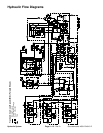
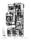
Forward Direction
When the Hi/Low switch isin the Low speed (4WD)posi-
tion and the traction pedal is pushed in theforward direc-
tion, oil from the piston pump passes through the
traction manifold. Oil flow from traction manifold port M1
drives the front wheel motors in the forward direction
and then returns to the piston pump. Oil flow from trac-
tion manifold port M2 is routed to the P1 port of the 4WD
manifoldwhereitisdirectedtothePD1cartridgeandout
ofthemanifoldtodrivetherearaxlemotorintheforward
direction. Oil returning from the rear motor re--enters the
4WD manifold at the M2 port. Flow passes through the
PD2 cartridge, through the CVcheck valve, out manifold
port P2 and back to the piston pump.
When going down a hill, the tractor becomes an over--
running load that drives the wheel and axle motors. In
this condition, the rear axle motor could lock up as the
oil pumped from the motor increases pressure as it re-
turns to the piston pump. To prevent rear wheel lock up,
an adjustable relief valve (RV) in the 4WD manifold re-
duces rear axle motor pressure created in down hill, dy-
namic braking conditions.
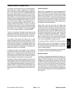
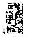
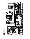
Reverse Direction
The traction circuit operates essentially the same in re-
verse Low speed (4WD) as it does in the forward direc-
tion. However, the flow through the circuit is reversed.
Oil flow from the piston pump is directed to the front
wheel motors and also to the 4WD manifold. The oil to
the front wheel motors drives them in the reverse direc-
tion and then returns to the piston pump through the
traction manifold. Theoil to the4WD manifold enters the
manifold at portP2 and flows through pressure reducing
valve (PR) which limits the down stream pressure to the
rear axle motor to 650 PSI (45 bar) so the rear wheels
will not scuff the turf during reverse operation. This re-
duced pressure flows through the PD2 cartridge and out
port M2 to the rear axle motor. Return oil from the rear
motor re--enters the 4WD manifold at port M1, flows
throughthePD1cartridge,exitsthemanifoldatportP1
and returns to the piston pump.
Hydraulic
System