


Groundsmaster 4000--D/4010--D Hydraulic SystemPage 4 -- 147
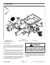
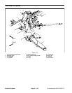
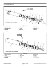
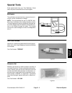
Removal (Fig. 114)
1. Park machine on a level surface, lower cutting
decks, stop engine, apply parking brake and remove
key from the ignition switch.
2. Read the General Precautions for Removing and
Installing Hydraulic System Components at the begin-
ning of the Service and Repairs section of this chapter.
3. To prevent contamination of hydraulic system during
lift cylinder removal, thoroughly clean exterior of cylin-
der and fittings.
WARNING
Make sure that front cutting deck is fully lowered
before loosening hydraulic lines from front deck
lift cylinders. If deck is not fully lowered as hy-
draulic lines are loosened, deck may drop unex-
pectedly.
NOTE: To ease installation, tag the hydraulic hoses to
show their correct position on the lift cylinder.
4. Disconnect hydraulic hoses from lift cylinder.
5. Remove lock nut, two (2)flat washers and cap screw
that secure the pin assembly to the lift arm. Remove pin
assembly from lift arm and cylinder shaft clevis w hich
will free lift cylinder from lift arm.
6. Remove one cotter pin from pivot pin that secures
upper end of lift cylinder to machine. Pull pivot pin from
frame and cylinder barrel clevis.
7. Remove lift cylinder from machine.
8. If hydraulic fittings are to be removed from lift cylind-
er,mark fitting orientationto allowcorrect assembly.Re-
move fittings from cylinder and discard O--rings.
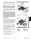
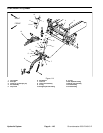
Installation (Fig. 114)
1. If fittings were removed from lift cylinder, lubricate
and place new O--rings onto fittings. Install fittings into
port openings using marks made during the removal
process to properly orientate fittings. Tighten fittings
(see Hydraulic Fitting Installation in the General Infor-
mation section of this chapter).
2. Position cylinder barrel clevisto frame and insert piv-
ot pin into frame and clevis. Secure pivot pin w ith cotter
pin.
3. Insert pin assembly through lift arm and cylinder
shaft clevis. Secure pin to lift armwith cap screw,two (2)
flat washers and lock nut.
4. Attach hydraulic hoses to lift cylinder (see Hydraulic
Hose and Tube Installation in the General Information
section of this chapter).
5. Fill reservoir with hydraulic fluid as required.
6. After assembly is completed, operate lift cylinder to
verify that hydraulic hoses and fittings are not contacted
by anything.
Hydraulic
System