


Groundsmaster 4000--D/4010--D Hydraulic SystemPage 4 -- 19
Mow
A four section gear pump is coupled to the piston (trac-
tion) pump. Hydraulic flow for the mow circuit is supplied
by two sections of the gear pump. The gear pump sec-
tion closest to the piston (traction) pump supplies hy-
draulic flow to the side cutting decks, while the next gear
pump section supplies the front cutting deck.
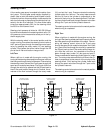
Each cutting deck is controlled by a hydraulic manifold
equipped with a solenoid control valve (S), bypass car-
tridge (LC1), brake cartridge (LC2) andtwo (2) relief car-
tridges (R V1 and RV2). Circuit pressure can be
measured at port (G) of the hydraulic manifold for each
cutting deck.
NOTE: To engage the mow circuit, the operator must
be in the operator seat, the cutting deck(s) must be fully
loweredandthetractionspeedmustbeintheLow
speed (4WD) position.
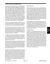
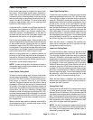
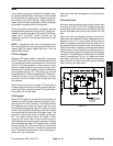
PTO Not Engaged
When the PTO switch is OFF or if the deck is raised with
the PTOswitch ON, the PTO manifold solenoid valve (S)
is not energized and the solenoid spool is in the neutral
position. This solenoid spool in neutral allows a small
amount of hydraulic flow toreturnto tank through a man-
ifold sensing line which causes a pressure increase that
shifts bypass cartridge LC1. The pump flow is routed
throughshifted LC1 and out manifold port P2. Brake car-
tridge LC2 remains in the unshifted position to prevent
any return flow from the deck motor to keep the motor
from rotating.
Return flow from the front and right PTO manifolds is
routedthroughthe oil cooler,oilfilterand then to the gear
pump input. Return flow from the left PTO manifold pro-
vides supply f or the right deck.
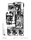
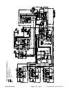
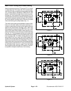
PTO Engaged
When the PTO switch is turned ON and the decks are
lowered, the PTO manifold solenoid valve (S) is ener-
gized by the TEC--5001 controller. This shifted solenoid
valve prevents any sense line flow through the valve
which allows the bypass cartridge LC1 to be in itsneutral
position. Gear pump flow entering the manifold is routed
out manifold port M1 and to the cutting deck motor. The
return flow from the deck motor re--enters manifold port
M2. The shifted solenoid valve (S) allows a small
amount of this return flow to return to tank through a
manifold sensing line which causes a pressure increase
that shifts brake cartridge LC2. Hydraulic flow is routed
through shifted LC2, out manifold port P2, through the
oil cooler and filter and then is routed to the gear pump
input. The deck m otor continues to rotate as long as so-
lenoid valve (S) is energized.
Deck motor case drain leakage returns to the hydraulic
reservoir.
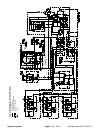
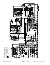
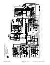
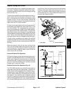
PTO Circuit Relief
Maximum mow circuit pressure is limited for each deck
by a relief valve (RV1) in the PTO manifold. The center
and left deck relief valves are set at 3000 PSI (207 bar)
and the right deck relief valve is set at 2000 PSI (138
bar).
Relief valve (RV1) and bypass cartridge (LC1) work to-
gether as a two stage relief. When increased circuit re-
sistance is met or if a cutting blade should strike an
object, the pressure increase is felt at the relief valve. If
the pressure should exceed the relief valve setting, the
relief valve will open, creating a small amount of hydrau-
lic flow to return to tank through a manifold sensing line.
This flow causes a pressure increase t hat shifts bypass
cartridgeLC1 and diverts circuit flow away from the deck
motor to manifold port P2 (Fig. 10). When circuit pres-
sure lowers, relief valve (RV1) closes which returns by-
pass cartridge LC1 back to its neutral position allowing
flow to return to the deck motor.
Figure 10
SOLENOIDSENERGIZED
RV1SHIFTED
LC1SHIFTED
DECKMOTORSTALLED
FRONTPTO
MANIFOLD
PUMPFLOW
RETURN
Hydraulic
System