


Rev. AGroundsmaster 4000--D/4010--D Hydraulic SystemPage 4 -- 17
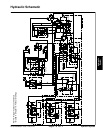
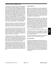
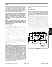
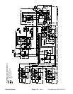
Raise Cutting Deck
A four section gear pump is coupled to the piston (trac-
tion) pump. The third gear pump section supplies hy-
draulic flow to both the steering and lift/lower circuits.
Hydraulic flow from this pump section is delivered to the
two circuits through a proportional flow divider that is lo-
cated in the fan drive manifold. This flow divider splits
pump flow approximately 50% for the steering circuit
and 50% for the lift/lower circuit.
A relief valve (RV1) located in the lift/lower manifold lim-
its lift/lower circuit pressure to 1600 PSI (110 bar). An
adjustable valve (RV2) in the lift/lower manifold main-
tains back pressure (counterbalance) on the deck lift
cylinders to allow some of the cutting deck weight to be
transferred to the traction unit to improve traction.
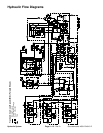
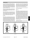
Each of the cutting decks (center, right and left) can be
raised independently with the use of three (3) switches
on the armrest console. Pressing the rear of a switch
provides an input for the TEC--5001 controller to raise a
cutting deck. The controller provides electrical outputs
to solenoids in the lift/lower manifold to allow appropri-
atevalveshifttocauseadecktoraise.
When the cutting decks are in a stationary position, all
solenoids in the lift/lower manifold are de--energized. In
this position, lift/lower circuit flow bypasses the lift cylin-
ders and is directed through the lift/lower manifold, oil fil-
ter and is then available for the traction charge circuit.
NOTE: To raise a cutting deck, the operator must be in
the operator seat.
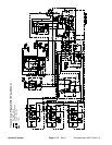
Raise Center Cutting Deck
To raise the center cutting deck, the rear of the center
console switch is depressed. The switch signal is an in-
put to the TEC--5001 controller which provides an elec-
trical output to solenoid valves S1 and S5 in the lift/lower
manifold. The energized solenoid valves shift to allow a
passage for circuit oil flow to the rod end of the center
deck lift cylinders. Shifted S1 prevents oil flow from by-
passing the lift cylinders. Shifted S5 allows an oil path to
the rod end of the front lift cylinders causing the lift cylin-
ders to retract and r aise the center cutting deck. An ori-
fice in manifold port C2 (.035) exists to control the raise
speed of the cutting deck. Oil from the barrel end of the
retracting cylinders returns to the hydraulic reservoir.
When the deck switch is released, the manifold sole-
noids are de--e nergized and the center deck lift cylin-
ders and center cutting deck are held in position.
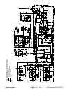
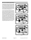
Raise Right Cutting Deck
To raise the right deck, the rear of the right console
switch is depressed as an input to the TEC--5001 con-
troller. The controller provides an electrical output to so-
lenoid valves S1 and S7 in the lift/lower manifold. The
energized solenoid valves shift to allow a passage for
circuit oil flow to the barrel end of the right deck lift cylin-
der. Shifted S1 prevents oil flow from bypassing the lift
cylinders. Shifted S7 allows an oil path through the ori-
fice in manifold port C6 and to the barrel end of the right
lift cylinder to extend the lift cylinder and raise the right
cutting deck. Oil from the extending cylinder is directed
through S8 ( de--energized), out manifold port CH, to the
oil filter and then to the traction charge circuit.
When the deck switch is released, the manifold sole-
noids are de--energized and the lift cylinder and right
cutting deck are held in position.
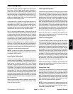
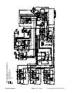
Raise Left Cutting Deck
To raise the left deck, the rear of the left console switch
is depressed as an input to the TEC--5001 controller.
The controller provides an electrical output to solenoid
valves S1 and S2 in the lift/lower manifold. The ener-
gized solenoid valves shift to allow a passage for circuit
oil flow to the barrel end of the left deck lift cylinder.
Shifted S1 prevents oil flow from bypassing the lift cylin-
ders. Shifted S2 allows an oil path through the orifice in
manifold port C4 and to the barrel end of the left lift cylin-
der to extend the lift cylinder and raise the left cutting
deck. Oil from the extending cylinder is directed through
S3 (de--energized), out manifold port CH, to the oil filter
and then to the traction charge circuit.
When the deck switch is released, the manifold sole-
noids are de--energized and the lift cylinder and left cut-
ting deck are held in position.
Hydraulic
System