Groundsmaster 4000--D/4010--DHydraulic System Page 4 -- 140
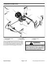
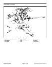
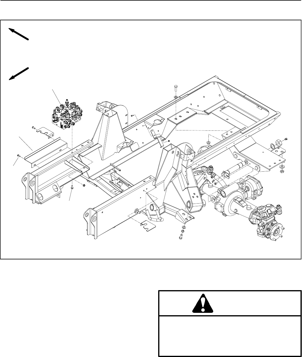
Lift/Lower Manifold
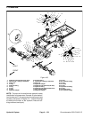
1. Lift/lower manifold
2. Flange head screw (2 used)
3. Washer head screw (2 used) 4. Splash shield
Figure 109
FRONT
RIGHT
2
4
3
1
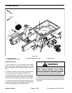
Removal (Fig. 109)
1. Park machine on a level surface, lower cutting
decks, stop engine, apply parking brake and remove
key from the ignition switch. Raise and support operator
seat.
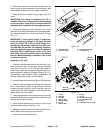
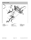
2. Remove controller cover and then support bracket
from the right side of the operator seat (Fig. 110).
3. Read the General Precautions for Removing and
Installing Hydraulic System Components at the begin-
ning of the Service and Repairs section of this chapter.
4. To prevent contamination of hydraulic system during
lift/lower manifold removal, thoroughly clean exterior of
manifold including fittings and hydraulic lines.
WARNING
Make sure that cutting decks are fully lowered
before loosening hydraulic lines, cartridge
valves or plugs from lift/lower manifold. If decks
are not fully lowered as manifold components
are loosened, decks may drop unexpectedly.
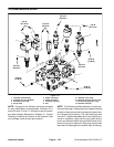
5. Label wire harness electrical connectors that attach
to manifold solenoid valve coils. Disconnect wire har-
ness connectors from the solenoid valve coilson lift/low-
er manifold.


