


Groundsmaster 4000--D/4010--DHydraulic System Page 4 -- 136
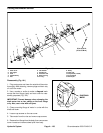
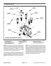
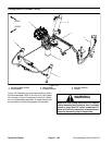
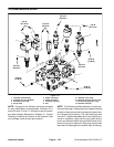
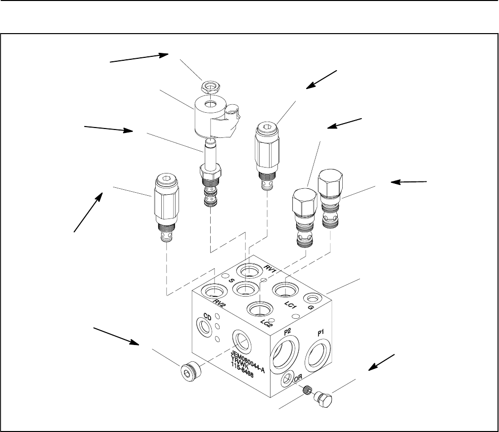
PTO Manifold Service
1. PTO manifold body
2. NWD SAE #4 plug with O --ring
3. Orifice (0.063) (port OR)
4. #8 zero leak plug with O--ring
5. Relief valve (port RV2)
6. Solenoid valve (port S)
7. Solenoid coil
8. Nut
9. Relief valve (port RV1)
10. Spool logic cartridge (port LC2)
11. Spool logic cartridge (port LC1)
Figure 107
10
8
9
4
2
6
7
1
5
3
11
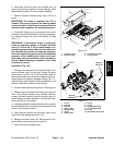
25 ft--lb
(34 N--m)
20 ft--lb
(27 N--m)
50 ft--lb
(67 N--m)
5 ft--lb
(6.7 N--m)
25 ft--lb
(34 N--m)
20 ft--lb
(27 N--m)
20 ft--lb
(27 N--m)
20 ft--lb
(27 N--m)
RH DECK PTO MANIFOLD SHOWN
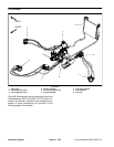
NOTE: The ports on the manifold are marked for easy
identification of components. Example: S is the deck so-
lenoid valve and P1 is the gear pump connection port
(see Hydraulic Schematic in Chapter 10 -- Foldout
Drawings to identify the function of the hydraulic lines
and cartridge valves at each port location).
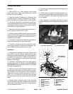
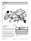
The manifolds for the three (3) cutting decks are very
similar. The front deck manifold does not include an ori-
fice (item 3). Note: When servicing the PTO manifolds,
DO NOT interchange parts from one manifold to anoth-
er.
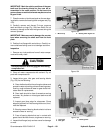
NOTE: The PTO manifold assembly includes zero leak
plugs. These plugs have a tapered sealing surface on
the plug head that isdesigned to resist vibrationinduced
plug loosening. The zero leakplugs alsohave an O--ring
as a secondary seal. If zero leak plug removal is neces-
sary, lightly rap the plug head using a punch and ham-
mer before using an allen wrench to remove the plug:
the impact will allow plug removal with less chance of
damage to the socket head of the plug.