


Groundsmaster 4000--D/4010--D Hydraulic SystemPage 4 -- 53
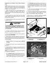
Procedure for PTO Relief Pressure Test
1. Make sure hydraulic oil is at normal operating tem-
perature by operating the machine under load for
approximately ten (10) minutes. Make sure the hydrau-
lic tank is full.
2. Park machine on a level surface with the cutting
decks lowered and off. Make sure engine is off and the
parking brake is applied.
CAUTION
Prevent personal injury and/or damage to equip-
ment. Read all WARNINGS, CAUTIONS and Pre-
cautions for Hydraulic Testing at the beginning
of this section.
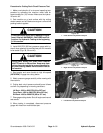
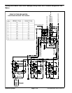
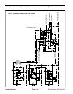
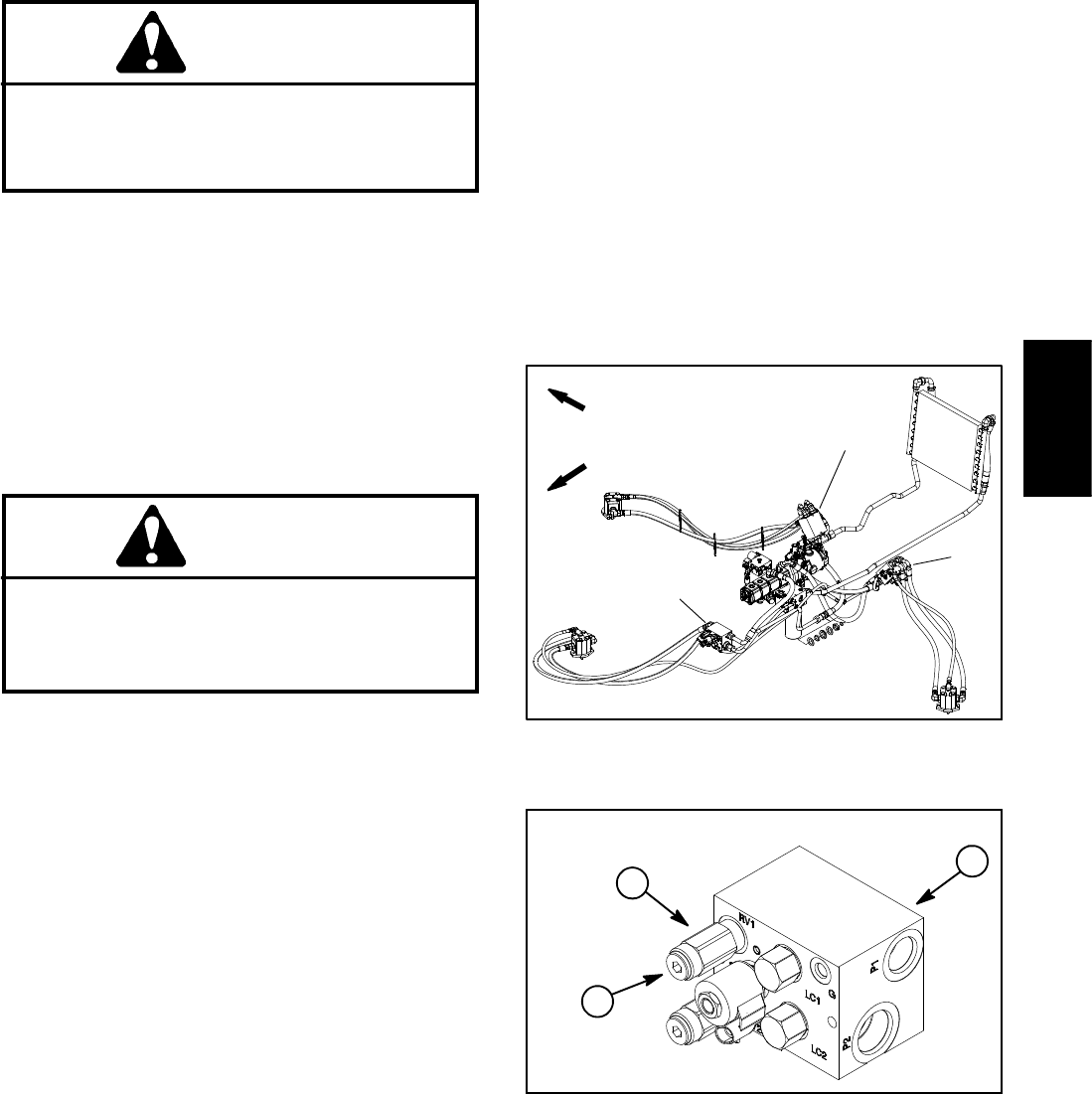
3. Locate deck manifold to be tested (Fig. 41). Discon-
nect hydraulic hose at deck manifold port (M1).
NOTE: Analternative tousing manifold port (M1)would
be to disconnect the inlet hydraulic hose to the deck mo-
tor.
4. Install tester (flow and pressure) in series with the
disconnected hose and hydraulic manifold port (M1) (or
motor inlet if hose was disconnected at deck motor).
Make sure the flow control valve on tester is fully open.
CAUTION
Cutting deck blades will rotate when lowered
with PTO switch in ON position. Keep away from
cutting decks during test to prevent personal in-
jury from rotating blades. Do not stand in front of
the machine.
5. Start engine and move throttle to high idle speed
(2870 RPM). Engage the cutting decks.
6. Watch pressure gauge carefully while slowly closing
the tester f low control valve to fully closed.
7. As the relief valve lifts, system pressure should be
approximately:
2900 to 3100 PSI (200 to 213 bar) for the front and
left decks
1900 to 2100 PSI (131 to 144 bar) for the right deck
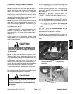
8. Fully open tester flow control valve and d isengage
cutting decks. Shut off engine and r ecord test results. If
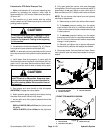
specification is not met, adjust or clean relief valve in
deck manifold port (RV1). Adjust relief valve as follows:
NOTE: Do not remove relief valve from the hydraulic
manifold for adjustment.
A. Remove cap on relief valve with an allen wrench.
B. To increase pressure setting, turn the adjust-
ment screw on the valve in a clockwise direction. A
1/8 turn on the screw willmake a measurable change
in relief pressure.
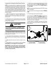
C. To decrease pressure setting, turn the adjust-
ment screw on the valve in a counterclockwise direc-
tion. A 1/8 turn on the screw will make a measurable
change in relief pressure.
D. Reinstall and tighten cap to secure adjustment.
Recheck relief pressure and readjust as needed.
9. Disconnect tester from manifold and hose. Recon-
nect hydraulic hose that was disconnected for test pro-
cedure.
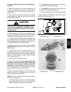
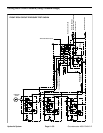
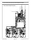
1. Front PTO manifold
2. LH PTO manifold
3. RH PTO manifold
Figure 41
FRONT
RIGHT
1
3
2
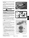
1. PTO manifold
2. PTO relief valve (RV1)
3. Relief valve cap
Figure 42
1
2
3
FRONT PTO MANIFOLD SHOWN
Hydraulic
System