


Groundsmaster 4000--D/4010--DHydraulic System Page 4 -- 126
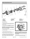
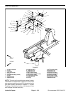
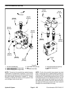
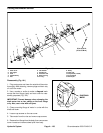
Fan Drive Manifold Service
1. Fan drive manifold body
2. #4 zero leak plug with O--ring (3 used)
3. Check valve (port CV)
4. #6 zero leak plug with O--ring (2 used)
5. Flow divider valve (port FD)
6. Nut
7. Solenoid coil (2 used)
8. Proportional relief valve (port TS)
9. Solenoid valve (port S1)
10. Nut
Figure 97
FRONT
UP
B
1
2
3
4
5
2
2
4
7
9
8
6
10
7
20 ft--lb
(27 N--m)
20 ft--lb
(27 N--m)
20 ft--lb
(27 N--m)
50 ft--lb
(67 N--m)
25 ft--lb
(34 N--m)
25 ft--lb
(34 N--m)
25 ft--lb
(34 N--m)
25 ft--lb
(34 N--m)
25 ft--lb
(34 N--m)
5 ft--lb
(6.7 N--m)
5 ft--lb
(6.7 N--m)
FRONT
UP
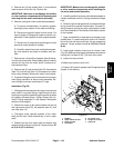
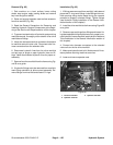
NOTE: The ports on the manifold are marked for easy
identification of components. Example: P1 and P2 are
gearpumpconnection ports andS1is the solenoidvalve
port (see Hydraulic Schematic in Chapter 10 -- Foldout
Drawings to identify the function of the hydraulic lines
and cartridge valves at each port).
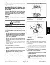
NOTE: The fan drive manifold uses several zero leak
plugs. These plugs have a tapered sealing surface on
the plug head that isdesigned to resist vibrationinduced
plug loosening. The zero leakplugs alsohave an O--ring
as a secondary seal. If zero leak plug removal is neces-
sary, lightly rap the plug head using a punch and ham-
mer before using an allen wrench to remove the plug:
the impact will allow plug removal with less chance of
damage to the socket head of the plug.