


Groundsmaster 4000--D/4010--D Page 5 -- 33 Electrical System
Main Power, Glow and Operator Cab Power (Groundsmaster 4010--D) Relays
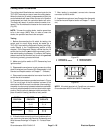
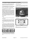
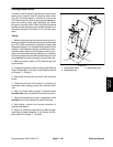
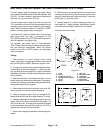
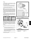
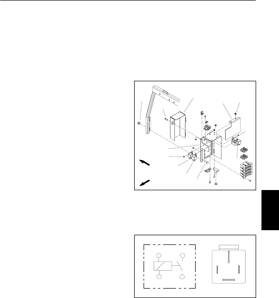
The main power, glow and operator cab power relays
are located atthe power center behindthe operator seat
(Fig. 39). The wire harness is attached to these relays
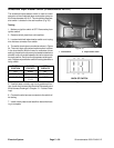
with a four (4) wire connector (Fig. 40).
The main power relay is used to provide current to the
TEC controllers and most of the fuse protected circuits
(operator seat, power point and optional electric equip-
ment). When the ignition switch is in the ON or START
position, the main power relay is energized.
The glow relay is used to provide current to the engine
glow plugs when the relay is energized by the
TEC--5002controller.TheTEC--5002 controls andmon-
itors the operation of the glow relay.
The operator cab power relay on Groundsmaster
4010--D machinesis used to provide currentto theoper-
ator cab electrical c omponents. When the ignition
switch is in the ON or START position, the cab power
relay is energized.
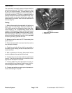
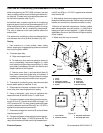
Testing
1. Park machine on a level surface, lower cutting
decks, stop engine, engage parking brake and remove
key from the ignition switch. Raise and support hood.
2. To make sure that machine operation does notoccur
unexpectedly, disconnect negative (--) cable from bat-
tery and then disconnect positive (+) cable from battery
(see Battery Service in the Service and Repairs section
of this chapter).
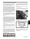
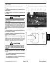
3. Remove cover (item 1) and heat shield (item 11)from
power center and locate relay to be tested. If necessary,
remove two ( 2) flange nuts and carriage screws that se-
cure power center to tank support.
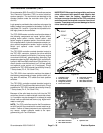
4. Disconnect wire harness connector from relay. Re-
move relay from mounting bracket for testing.
5. Using a multimeter, verify that coil resistance be-
tween terminals 86 and 85 is approximately 72 ohms.
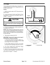
6. Connect multimeter (ohmssetting) leads to relayter-
minals 30 and 87. Ground terminal 86 and apply +12
VDC to terminal 85. The relay should make and break
continuity between terminals 30 and 87 as +12 VDC is
applied and removed from terminal 85.
7. Disconnect voltage and test leads from the relay ter-
minals.
8. Secure relay to mounting bracket and connect wire
harness connector to relay.Secure power center totank
support if it was removed. Install cover (item 1) and heat
shield (item 11) to power center.
9. Connect positive (+) cable to battery and then con-
nect negative (--) cable to battery (see Battery Service
in the Service and Repairs section of this c hapter).
10.Lower and secure hood.
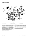
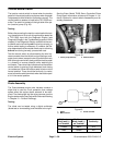
1. Cover
2. Screw
3. Flange nut (2 used)
4. Carriage screw (2 used)
5. Screw
6. Mount
7. Lock nut
8. Main power relay
9. Glow relay
10. Cab power relay
11. Heat shield
12. Screw (2 used)
Figure 39
2
3
4
5
1
8
7
6
9
10
FRONT
RIGHT
11
12
Figure 40
86 87
85 30
85 86
87
30
Electrical
System