


Groundsmaster 4000--D/4010--D Hydraulic SystemPage 4 -- 87
5. Disconnect wire harness connector from neutral
switch on piston pump.
6. Read the General Precautions for Removing and
Installing Hydraulic System Components at the begin-
ning of the Service and Repairs section of this chapter.
7. Forinstallationpurposes,label all hydraulic lines that
connect to gear pump and piston pump.
8. Put a drain pan below the pump assembly. Remove
hydraulic hoses and fittings connected to piston and
gear pumps. Put plugs or caps on disconnected hydrau-
lic hoses to prevent contamination of the system. Put
plugs in open ports of pumps.
NOTE: If fuel tank is removed from the machine, the
gear pump and piston pump can be removed as a com-
plete assembly.
9. Remove gear pump from machine (see Gear Pump
Removal in this section).
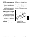
10.Support the piston pump to prevent it from falling
while removing two (2) cap screws and washers retain-
ing pump assembly to engine flywheel plate. Carefully
pull pump assembly from flywheel plate and raise it out
of the machine.
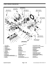
Installation (Fig. 68)
IMPORTANT: To prevent spring coupler damage,
make sure that piston pump is properly supported
anddoesnot put side load into coupler duringpump
installation.
1. Carefully raise piston pump into the machine, align
pump input shaft to spring coupler on engine and posi-
tion it to the engine flywheel plate. Support pump to pre-
vent it from producing any side load into coupler and
also to align pilot diameter of pump to flywheel plate
bore.
2. Apply Loctite #242 (or equivalent) to threads of cap
screws (item 6) used to secure piston pump to engine
flywheel plate.
3. While maintaining pump alignment with spring cou-
pler and flywheel plate, install two (2) cap screws and
washers to secure piston pump to engine. Torque
screws from 79 to 84 ft--lb (108 to 113 N--m).
4. Install gear pump to piston pump (see Gear Pump
Installation).
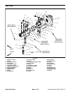
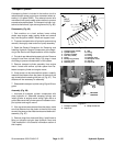
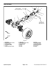
5. Position traction rod to control arm on piston pump
by installing cap screw, spacer and lock nut (Fig. 69).
6. Connect wire harnessconnector to neutralswitch on
traction pump.
7. Remove plugs or caps from disconnected hydraulic
hoses and open ports of the pump assembly. Install fit-
tings and hoses to correct location on gear and piston
pumps (see Hydraulic Fitting Installation and Hydraulic
Hose and Tube Installation in the General Information
section of this chapter).
8. Lower machine to ground.
9. Install new filter and fill hydraulic reservoir with cor-
rect oil.
IMPORTANT: Refer to Traction Circuit Component
Failure in the General Information section of this
chapter forinformation regarding the importance of
removing contamination from the traction circuit.
10.Disconnect engine run solenoid electrical connector
to prevent engine from starting. Prime pumps by turning
ignition key switch to crank engine for ten (10) seconds.
Let starter cool and then repeat cranking procedure
again.
11.Connect engine run solenoid electrical connector,
start the engine and check for proper operation.
12.Properly fill hydraulic system (see Charge Hydraulic
System in this section).
13.Stop engine and check for hydraulic oil leaks. Check
hydraulic reservoir oil level.
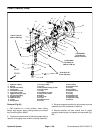
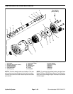
1. Piston pump
2. Cap screw
3. Pump control arm
4. Spacer
5. Lock nut
6. Jam nut
7. Traction rod
8. Rod end
Figure 69
1
2
4
5
6
3
7
8
Hydraulic
System