


Groundsmaster 4000--D/4010--D Hydraulic SystemPage 4 -- 121
8. Remove anddiscard back--up gaskets and pressure
seals from wear plates.
9. Turn front flange over, with seal side up.
IMPORTANT: Make sure not to damage the front
flange counter bore w hen removing the seals from
the front flange.
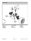
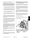
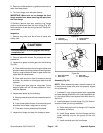
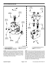
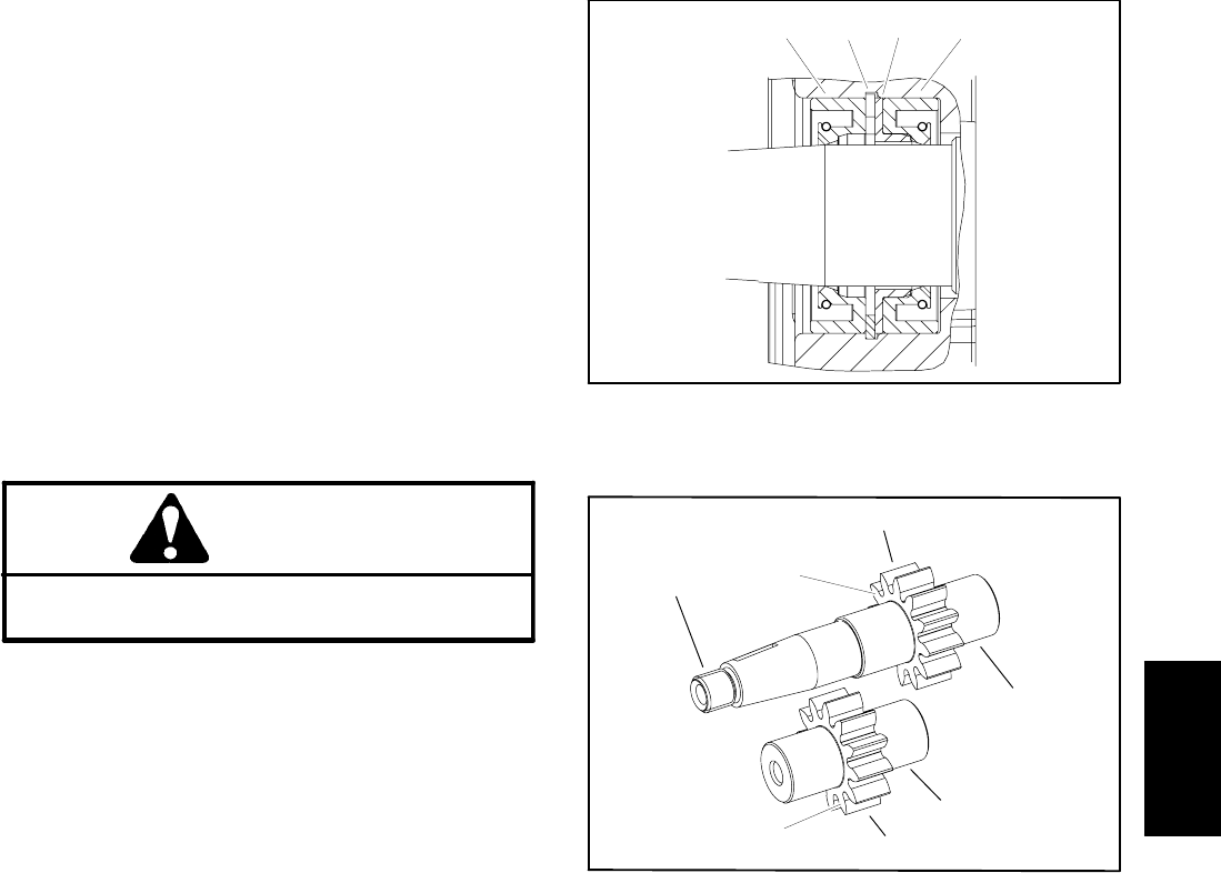
10.Carefully remove dust seal, retaining ring, flange
washer and shaft seal from the front flange (Fig. 93).
Note orientation of seal lips during removal. Discard re-
moved seals.
Inspection
1. Remove any nicks and burrs from all parts with
emery cloth.
CAUTION
Use eye protection such as goggles when using
compressed air.
2. Clean all parts with solvent. Dry all parts with com-
pressed air.
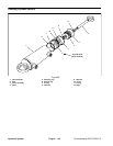
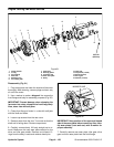
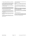
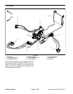
3. Inspect drive gears and idler gears for the following
(Fig. 94):
A. Gear shafts should be free of rough surfaces and
excessive wear at bushing points and sealing areas.
Scoring, rough surfaces or wear on gear shafts indi-
cates need for replacement.
B. Gear teeth should be free of excessive scoring
and wear. Any broken or nicked gear teeth must be
replaced.
C. Inspect gear face edge for sharpness. Sharp
edges of gears will mill into wear plates and, thus,
must be replaced.
4. Inspect wear plates for the following:
A. Bearingareas should not have excessivewear or
scoring.
B. Face of wear plates that are in contact with gears
should be free of wear, roughness or scoring.
C. Thickness of wear plates should be equal.
5. Inspect front flange and body for damage or wear.
1. Dust seal
2. Retaining ring
3. Flange washer
4. Shaft seal
Figure 93
1
2
3
4
1. Gear shaft spline
2. Gear shaft
3. Gear teeth
4. Gear face edge
Figure 94
1
3
4
2
3
4
2
Assembly (Fig. 91)
NOTE: When assembling motor, check the marker line
on each part to make s ure parts are properly aligned
during assembly.
1. Lubricate O--rings, pressure seals,back--up gaskets
and wear plate grooves with a thin coat of petroleum jel-
ly. Lubricate all other internal parts freely w ith clean hy-
draulic oil.
2. Install new seals into front flange (Fig. 93). Note ori-
entation of seal lips during installation:
A. Press s haft seal into front flange until it reaches
the bottom of the bore.
B. Install flange washer into front flange and then
install retaining ring into the groove of the front
flange.
C. Install new dust seal into front flange.
Hydraulic
System