


Groundsmaster 4000--D/4010--D Page 7 -- 5 Chassis
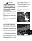
CAUTION
When changing attachments, tires or perform-
ing other service, use correct jacks and sup-
ports. Make sure machine is parked on a solid,
level surface such as a concrete floor. Prior to
raising machine, remove any attachments that
may interfere with the safe and proper raising of
themachine.Alwayschockorblockwheels.Use
jack stands to support the raised machine. If the
machine is not properly supported by jack
stands, the machine may move or fall, which
may result in personal injury.
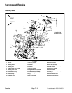
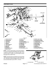
3. Chock rear wheels and jack up front of machine.
Support machine on jack stands.
4. Remove front wheel next to lift arm that is to be re-
moved.
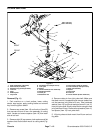
5. Remove cap screw, washers and lock nut that se-
cure lift cylinder pin to lift arm. Remove pin and separate
lift cylinder and lift arm.
6. Remove lock nut that secures lift arm pin.Support lift
arm and slide pin from frame and lift arm. Remove lift
armfromframe.
7. Remove height--of--cut chain, ball joint mount and
ball joint from removed lift arm as required.
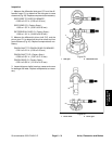
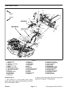
Installation (Fig. 2)
1. Position lift arm to frame and insert lift arm pin. En-
gage roll pin into frame slots and install lock nut on pin.
Torque lock nut from 60 to 70 ft--lb (81 to 94 N--m).
2. Align lift cylinder with lift arm. Slide pin through lift
arm and cylinder end. Secure pin with cap screw, wash-
ers and lock nut.
3. Install front wheel assembly and lower machine to
the ground. Make sure that wheel lug nuts are torqued
from 85 to 100 ft--lb (115 to 135 N--m).
4. If sensing plate (item 32) was removed from lift arm,
secure plate fully forward in lift arm slot.
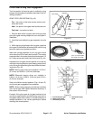
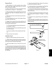
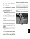
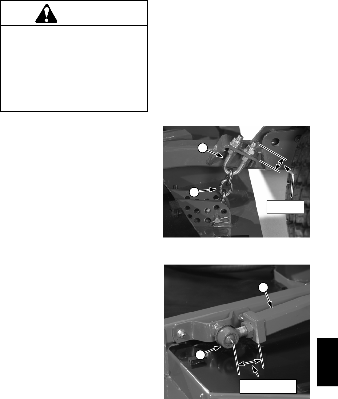
5. If height--of--cut chain u--bolt was removed from lift
arm, assemble u--bolt so that threaded portion extends
0.870” (22.1 mm) above mounting plate on lift arm (Fig.
3).
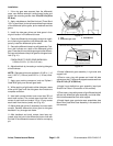
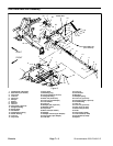
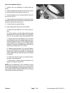
6. If removed, install ball joint to lift arm. Distance from
end of liftarm tocenter of ball jointshouldbe from 2.210”
to 2.390” (56.1 to 60.7 mm) (Fig. 4). Make sure that ball
joint is horizontal and that stud is centered in ball joint.
Install deck before torquing ball joint jam nut (item 24).
7. Installballjointmount to ball joint with slotted hex nut.
Torque nut from 90 to 100 ft--lb (123 to 135 N--m) while
aligning cotter pin holes. Install cotter pin.
8. Install front cutting deck (see Front Cutting Deck
Installation in Chapter 8 -- Cutting Decks).
9. If ball joint wasremoved from lift arm,torque ball joint
jam nut from 150 to 175 ft--lb (203 to 237 N--m).
10.Lubricate lift arm grease fittings.
11.After assembly is completed, raise andlower the cut-
ting deck to verify that hydraulichoses andfittings do not
contact anything.
12.Check height--of--cut and deck pitch adjustment.
1. U--bolt 2. Height--of--cut chain
Figure 3
1
2
0.870”
(22.1 mm)
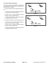
1. Lift arm 2. Ball joint
Figure 4
1
2
2.210” to 2.390”
(56.1 to 60.7 mm)
Chassis