


Groundsmaster 4000--D/4010--D Page 3 -- 5 Kubota Diesel Engine
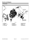
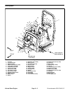
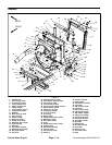
Removal (Fig. 1)
1. Park machine on a level surface, lower cutting
decks, stop engine, apply parking brake and remove
key from the ignition switch.
2. Raise and support hood.
3. Remove air cleaner components as needed using
Figure 1 as a guide.
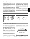
Installation (Fig. 1)
IMPORTANT: Any leaks in the air filter system will
cause serious engine damage. Make sure that all air
cleaner components are in good condition and are
properly secured during assembly.
1. Assemble air cleaner system using Figure 1 as a
guide.
A. If service indicator (item 4) and adapter (item 15)
wereremovedfrom air cleanerhousing,apply thread
sealant to adapter threads before installing adapter
and indicator to housing. Install adapter so that
groovesinadapterhexand adapter filter element are
installed toward service indicator (Fig. 3). Torque in-
dicator from 12 to 15 in--lb (1.4 to 1.6 N--m).
B. When securing air cleaner in air cleaner strap,
tighten cap screws (item 14) only enough to prevent
air cleaner from rotating in strap.
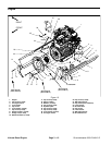
2. When installing air cleaner hose (item 1) between air
cleaner and turbo--charger (Fig. 4):
A. Make sure that hose does not contact engine
valve cover. To ensure clearance, move and/or ro-
tate air cleaner body in air cleaner strap.
B. Position hose to allow maximum clearance be-
tween air cleaner hose and muffler bracket.
3. Lower and secure hood.
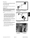
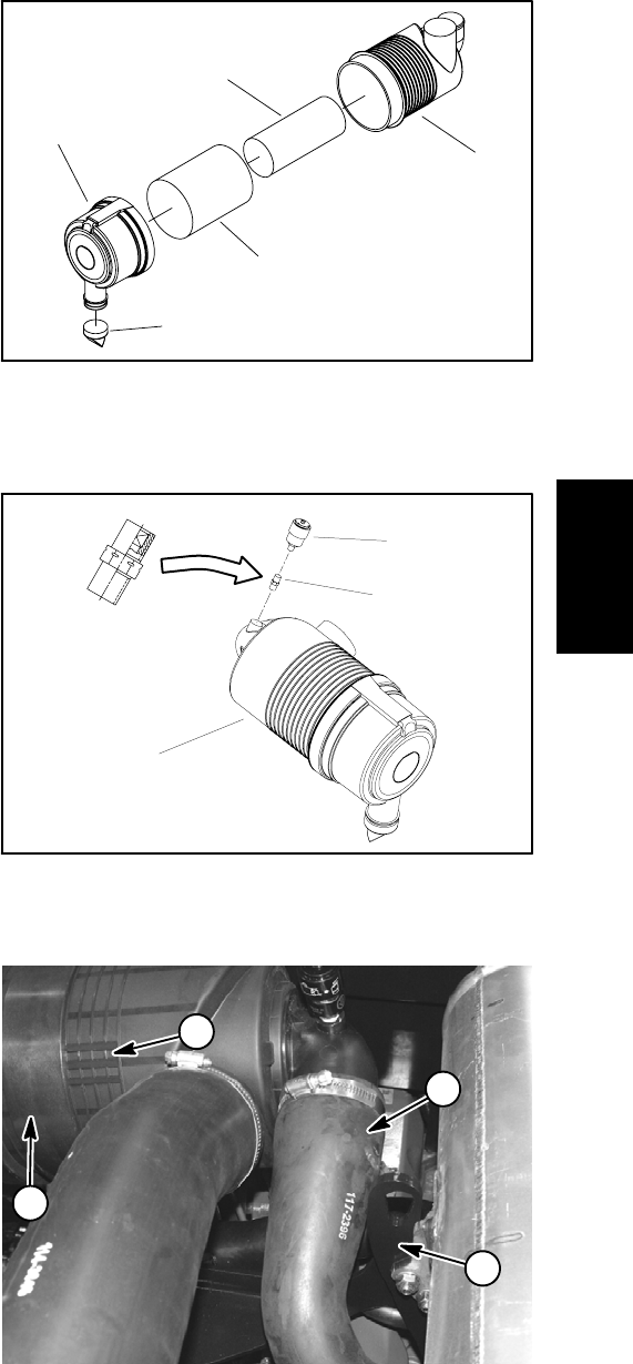
Figure 2
1. Air cleaner housing
2. Safety filter element
3. Air filter element
4. Air cleaner cover
5. Vacuator valve
1
3
2
4
5
Figure 3
1. Air cleaner assembly
2. Service indicator
3. Adapter
1
3
2
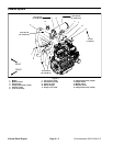
Figure 4
1. Air cleaner hose
2. Muffler bracket
3. Air cleaner strap
4. Air cleaner slots
1
2
3
4
Kubota
Diesel Engine