


Groundsmaster 4000--D/4010--D Page 6 -- 5 Axles, Planetaries and Brakes
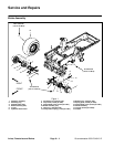
Removal (Fig. 1)
1. Park machine on a level surface, lower cutting
decks, stop engine and remove key from the ignition
switch.
2. Drain oil fromplanetary wheeldrive/brake assembly.
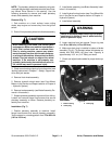
CAUTION
When removing front wheel, use correct jacks
and supports.Make sure machine is parkedon a
solid, level surface such as a concrete floor.
Prior to raising machine, remove any attach-
ments that may interfere with the safe and prop-
er raising ofthe machine. Alwayschock or block
wheels. Use jack stands to support the raised
machine. If the machine is not properly sup-
ported byjack stands, the machine maymove or
fall, which may result in personal injury.
3. Chock rear wheels and jack up front of machine (see
Jacking Instructions in Chapter1 -- Safety). Support ma-
chine with jack stands.
4. Remove front wheel assembly.
5. Remove hydraulic wheel motor (see Front Wheel
Motors in the Service and Repairs section of Chapter 4
-- Hydraulic System).
6. Disconnect brake link assembly from brake lever,
frame bracket and pull rod on brake assembly (Fig. 2).
7. Support brake assembly to prevent it from falling.
8. Remove flange head screws (item 9) securing brake
assembly to frame.
9. Remove brake assembly from machine. Be careful
to not drop splined brake shaft ( item 3) as brake assem-
bly is removed.
10.Remove splined brake shaft from brake assembly.
11.Remove and discard gasket (item 18). Make sure
that all gasket material is removed from both brake and
planetary assemblies.
12.Complete brake inspection and repair (see Brake In-
spection and Repair in this section).
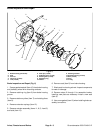
Installation (Fig. 1)
1. Install splined brake shaft (item 3) into brake assem-
bly. NOTE: The stepped end of the splined brake shaft
must be aligned toward the hydraulic wheel motor (Fig.
4).
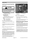
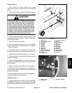
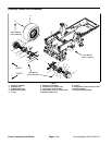
1. Brake lever
2. Thrust washer (2 used)
3. Flat washer
4. Lock nut
5. Bushing
6. Clevis pin
7. Lock nut
8. Cap screw
9. Brake link
10. Rod end (LH thread)
11. Jam nut (LH thread)
12. Hex link
13. Flanged spacer
14. Compression spring
15. Brake link
16. Brake assembly
17. Jam nut
18. Spring plate
19. Jam nut
20. Brake cable
21. Flat washer
22. Cotter pin
23. Screw (2 used)
24. Cable bracket
25. Frame r ail
Figure 2
2
3
6
8
9
10
11
13
1
5
7
12
14
15
16
17
18
19
20
4
21
22
25
24
23
9
22
21
6
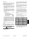
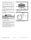
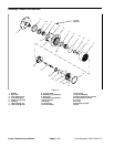
1. Brake housing
2. Check plug
3. Brake link assembly
Figure 3
3
1
2
Axles, Planetaries
and Brakes