


Groundsmaster 4010--D Operator CabPage 9 -- 5
5. Disconnect compressor electrical connector from
machine wire harness.
6. Read the General Precautions for Removing and
Installing Air Conditioning System Components at the
beginning of the Service and Repairs section of this
chapter.
CAUTION
The air conditioning system is under high pres-
sure. Do not loosen any system fitting or compo-
nent until after the system has been completely
discharged by a certified A/C service technician.
7. Have refrigerant evacuated from air conditioning
system by a certified A/C service technician.
8. Label and remove hoses from compressor. Immedi-
atelycaphosesandfittingsto preventmoisture and con-
taminants from entering the system.
9. Support compressor to prevent it from shifting or fal-
ling.
NOTE: There may be shims mounted between com-
pressor and compressor arm. When removing com-
pressor, note shim location and quantity for assembly
purposes.
10.Remove fasteners and spacers that secure com-
pressor to compressor mount and compressor arm.
IMPORTANT: To prevent compressor oil from filling
the compressor cylinders, keep compressor in the
same orientation as the installed position.
11.Carefully remove compressor from engine and ma-
chine.
NOTE: Thereplacement of the drier--receiver is recom-
mended whenever A/C compressor is removed from the
system (see Heater and Evaporator Assembly in this
section).
NOTE: The air conditioning compressor used on the
Groundsmaster 4010--D is a Sanden model SD5H09.
For air conditioning compressor repair procedures, see
the SD Compressor Service Guide at the end of this
chapter.
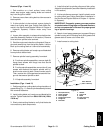
Installation (Fig. 1)
1. Position compressor to c ompressor mountandcom-
pressor arm.
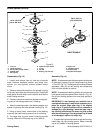
2. The clearance between the c ompressor mounting
flanges and pivot plate must be less than 0.004” (0.10
mm). If necessary, install shims between compressor
flanges and pivot plate to adjust clearance. See Parts
Catalog for shim kit.
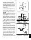
3. Secure compressor to compressor mount and com-
pressor arm with removed fasteners and spacers. Do
not fully tighten fasteners.
IMPORTANT: After the compressor has been
installed, make sure to rotate the compressor drive
shaft several times to properly distribute oil in the
compressor. Compressor damage due to oil slug-
ging can occur if this procedure is not performed.
4. Manually rotate the compressor drive shaft at least
ten (10) revolutions to make sure that no compressor oil
is in the compressor cylinders.
5. Place drive belt onto compressor pulley.
6. Tension compressor drivebelt with idler pulley. Make
sure to tighten lock nut to secure belt adjustment.
7. Remove caps that were placed on hoses and fittings
during the removal process. Using labels placed during
removal, properly secure hoses to compressor.
8. Connect compressor electrical connector to ma-
chine wire harness.
9. Have a certified air conditioning service technician
evacuate the air conditioning system completely, prop-
erly recharge the system with R134a refrigerant and
then leak test the system. A/C system capacity is 1.25
pounds of R134a refrigerant.
10.Lower and secure hood.
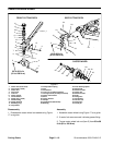
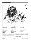
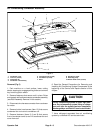
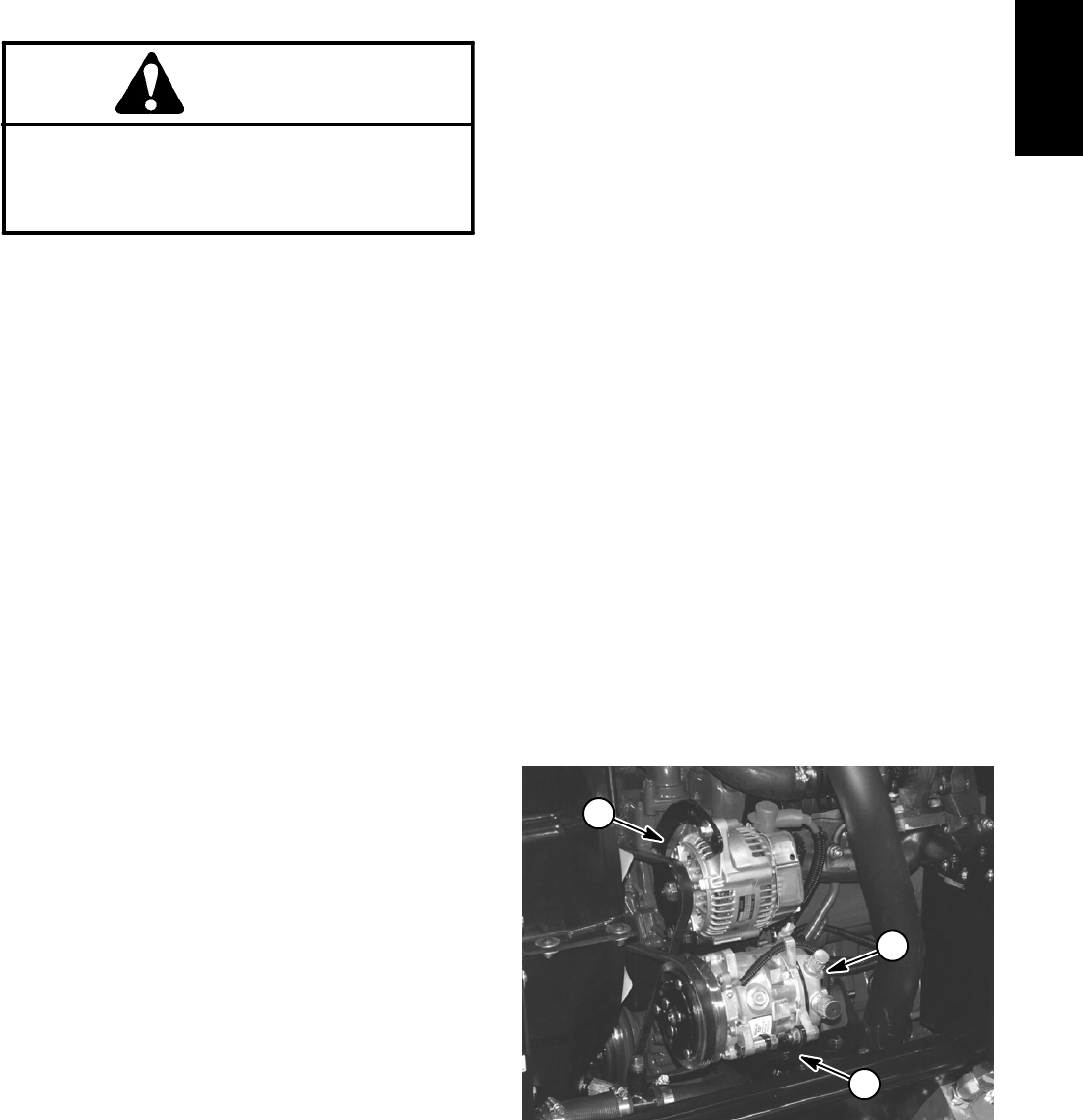
1. A/C compressor
2. Alternator
3. Compressor arm
Figure 2
1
2
3
Operator
Cab