


Groundsmaster 4000--D/4010--DPage 6 -- 22Axles, Planetaries and Brakes
Bevel Gear Case and Axle Case
The following procedures assume the rear axle assem-
bly has been removed from the machine.
Removal
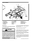
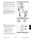
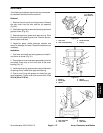
1. Remove the mounting screws, nuts and lock wash-
ers. Remove the bevel gear case/axle case assembly
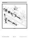
and O-ring from the axle s upport (Fig. 17).
2. Mark both right and left bevel gear case/axle case
assemblies.
IMPORTANT: Do not interchange right and left bev-
el gear case/axle case assemblies.
1
2
3
4
5
6
1. Cap screw (4 used)
2. Lock nut (2 used)
3. Lock washer (2 used)
4. Axle support
5. Bevel gear case/axle
case assembly
6. O-ring
Figure 17
35 to 41 ft--lb
(47to56N--m)
35 to 41 ft--lb
(47to56N--m)
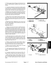
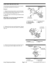
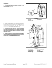
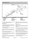
3. Remove the axle cover mounting screws. Remove
theaxlecoverfromtheaxlecaseasanassembly
(Fig. 18).
1. Axle case
2. Axle cover assembly
3. Screw (6 used)
4. O-ring
Figure 18
1
2
3
4
17 to 20 ft--lb
(23to27N--m)
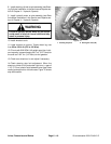
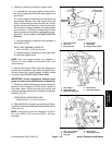
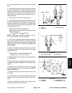
4. Remove the axle case s upport mountingscrews, the
axle case support and the support shims (Fig. 19).
1. Axle case
2. Axle case support
3. Screw (2 used)
4. Support shim
Figure 19
1
2
3
4
57 to 67 ft--lb
(77to91N--m)
Thread--locking
Compound