


Groundsmaster 4000--D/4010--D Hydraulic SystemPage 4 -- 141
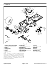
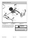
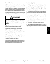
6. Disconnect hydraulic lines from manifold and put
caps or plugs on open hydraulic lines and fittings. Label
disconnected hydraulic lines for proper installation.
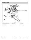
7. Remove lift/lower manifold using Figure 109 as a
guide.
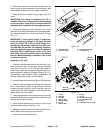
IMPORTANT: The fitting in manifold port C2 in-
cludes a .070 orifice to control the lowering speed
of the front deck. If this fitting is removed from the
manifold, label its position for assembly purposes.
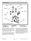
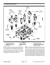
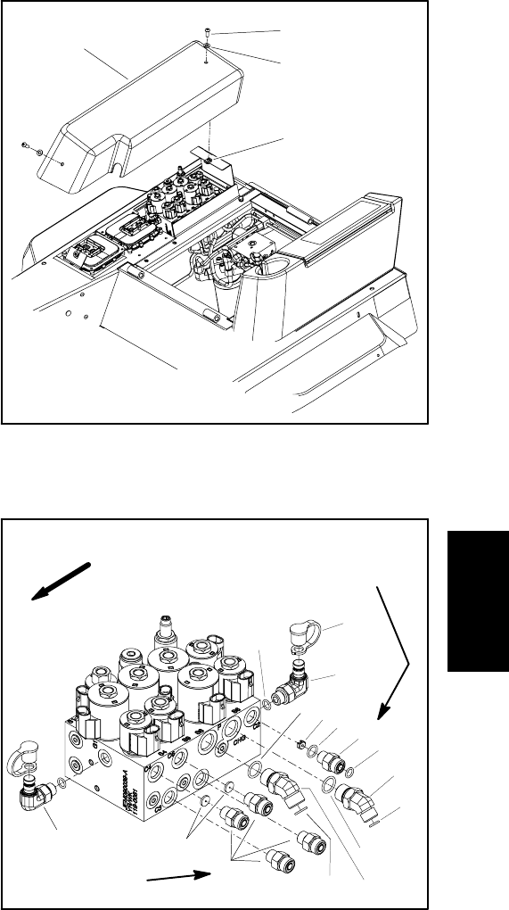
8. If hydraulic fittings are to be removed from control
manifold, mark fitting orientation toallow correctassem-
bly. Remove fittings from valve and discard O--rings
(Fig. 111).
IMPORTANT: A flow control orifice is placed be-
neath the hydraulic fittings in lift/lower manifold
ports C2, C4 and C6. If any of these fittings is re-
moved from the manifold, make sure to remove ori-
fice and label its position for assembly purposes.
Also note location of groove in orifice for assembly
purposes. When installing the orifice in the man-
ifold, make sure that the orifice is flat in the base of
the port. Manifold damage is possible if the orifice
is cocked in the port.
Installation (Fig. 109)
1. If fittings were removed from control manifold, lubri-
cate and place new O--rings onto fittings. Correctly
place orifice in port C2, C4 or C6 if removed. Install fit-
tings into port openings using marks made during there-
moval process to properly orientate fittings (Fig. 111).
Tighten fittings (see Hydraulic Fitting Installation in the
General Information section of this chapter).
2. Install lift/lower manifold using Figure 109 as a guide.
3. Remove caps and plugs from fittings and hydraulic
lines. Using labels placed during manifold removal,
properly connect hydraulic lines to manifold (see Hy-
draulic Hose and Tube Installation in the General Infor-
mation section of this chapter).
4. Using tags placed during manifold removal,correctly
connect wire harness connectors to the solenoid valve
coils on the lift/lower manifold.
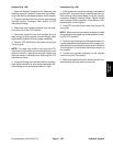
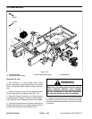
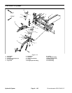
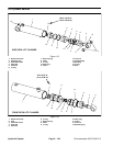
5. Install support bracket and controller cover to the
right side of the operator seat (Fig. 110).
6. Make sure hydraulic tankis full. Add correctoil if nec-
essary before returning machine to service.
7. Lower and secure operator seat.
1. Controller cover
2. Screw (2 used)
3. Flat washer (2 used)
4. U--nut (2 used)
Figure 110
2
3
1
4
1. O--ring
2. Dust cap
3. Test port
4. Orifice (.063)
5. Straight fitting
6. O--ring
7. Orifice (.035)
8. O--ring
9. O--ring
10. 45
o
hydraulic fitting
11. 45
o
hydraulic fitting
12. O--ring
13. Fitting with orifice (.070)
Figure 111
2
3
6
1
5
4
7
3
13
8
9
10
11
6
12
25 ft--lb
(34 N--m)
9
FRONT
25 ft--lb
(34 N--m)
Hydraulic
System