


Groundsmaster 4000--D/4010--D Hydraulic SystemPage 4 -- 119
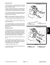
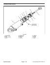
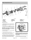
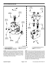
5. Remove four (4) c ap screws (item 11) and washers
used to secure fan to fan hub. Remove fan.
IMPORTANT: Make sure to not damage the radiator
or other machine components while loosening and
removing the fan motor and bracket assembly.
6. Remove cooling fan motor and bracket assembly.
A. To prevent contamination of hydraulic system,
thoroughly clean exterior of fan motor and fittings.
B. Disconnect hydraulic hoses from fan motor. Put
caps or plugs on fittings and hoses to prevent con-
tamination. Label hydraulic lines for proper assemb-
ly.
C. Remove six ( 6) cap screws and flange nuts that
secure fan motor bracket to radiator.
D. Carefully remove fan motor and bracket assem-
bly from machine and place on suitable work sur-
face.
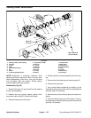
7. Remove hex nut (item 9) andwasher (item8) that se-
cure fan hubto fan motor.Use suitable puller to carefully
remove fan hub from fan motor shaft. Locate and re-
trieve woodruff key.
8. Remove two (2) cap screws (item 20), flat washers
(item 21) and lock nuts (item 14) that secure fan motor
to fan motor bracket. Remove fan motor from bracket.
9. If hydraulic fittings are to be removed from fan motor,
mark fitting orientation to allow correct assembly. Re-
move fittings from motor and discard O--rings.
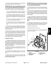
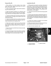
Installation (Fig. 89)
1. If fittings were removed fromfan motor, lubricate and
place new O--rings onto fittings. Install fittings into port
openingsusingmarks madeduringthe removalprocess
to properly orientate fittings. Tighten fittings (see Hy-
draulic Fitting Installation in the General Information
section of this chapter).
2. Position fan motor to fan motor bracket and secure
with cap screws (item 20), flat washers (item 21) and
lock nuts (item 14).
3. Thoroughly clean tapered surfaces of fan motor
shaft and fan hub. Place woodruff key in slot in motor
shaft.
4. Position fan hub onto motor shaft and secure with
washer (item 8) and hex nut (item 9). Torque nut from 27
to 33 ft--lb (37 to 44 N--m).
IMPORTANT: Make sure to not damage the radiator
or other machine components while installing the
fan motor and bracket assembly.
5. Carefully position fan motor andbracket assembly to
radiator and secure with six (6) cap screws and flange
nuts.
6. Remove caps and plugs placed in hoses and fittings
during removal to prevent contamination. Connect hy-
draulic hoses to cooling fan motor (see Hydraulic Hose
and Tube Installation in the General Information section
of this chapter).
7. Apply Loctite #242 (or equivalent) to threads of cap
screws (item 11) used to secure fan to fan hub. Position
fan to fan hub and secure with four (4) cap screws and
washers. Torque screws from 12 to 14 ft--lb (17 to 18
N--m).
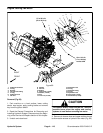
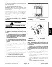
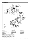
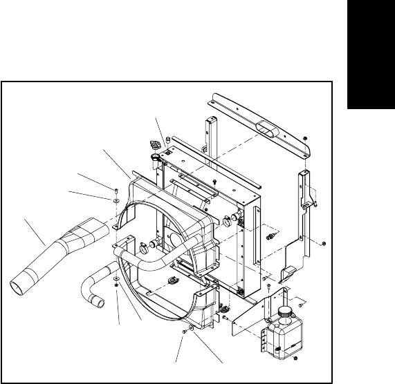
8. Install upper radiator shroud and air cleaner hose
(Fig. 90). Make sure that clearance betweenshroud and
cooling fan is at least 0.180” (4.6 mm) at all points.
9. Lower and secure hood.
10.Make sure hydraulic tank is full.
11.Properly fill hydraulic system (see Charge Hydraulic
System in this section).
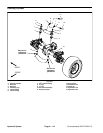
1. Radiator
2. Upper radiator shroud
3. Screw (4 used)
4. Flat washer
5. Air cleaner hose
6. Flange nut (4 used)
7. Cap screw
Figure 90
3
5
6
4
7
1
2
4
4
Hydraulic
System