


Rev. AGroundsmaster 4000--D/4010--D Hydraulic SystemPage 4 -- 47
Procedure for Rear Traction Circuit (RV) Relief Pres-
sure Test
1. Make sure hydraulic oil is at normal operating tem-
perature by operating the machine under load for
approximately ten (10) minutes. Make sure the hydrau-
lic tank is full.
2. Park machine on a level surface with the cutting
decks lowered and off. Make sure engine is off and the
parking brake is applied.
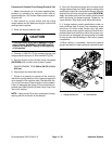
CAUTION
Prevent personal injury and/or damage to equip-
ment. Read all WARNINGS, CAUTIONS and Pre-
cautions for Hydraulic Testing at the beginning
of this section.
3. Measure and record traction circuit pressure redu-
cing valve (PR) pressure (see Traction Circuit Pressure
Reducing Valve (PR) Pressure Test in this section).
4. Connect a 1000 PSI (70 bar) pressure gauge to test
port on 4WD manifold under radiator. This is the same
pressure gaugeposition as used to measure traction cir-
cuit pressure reducing valve (PR) pressure.
5. Start the engine and put throttle at high idle speed
(2870 RPM). Make sure that Hi/Low switch is in the Low
(4WD) position.
6. Operate the machine in Low speed (4WD) with the
cutting decks lowered. Drivedownaslopeinaforward
direction, decrease pressure on the traction pedal and
monitor the pressure gauge. Pressure should increase
until the relief valve lifts.
7. Stop engine and record test results.
8. Relief (RV) pressure should be approximately 750
PSI (52 bar) and at least 100 PSI (7 bar) higher than
the traction circuit pressure reducing valve (PR)
pressure (e.g. if the pressure reducing valve (PR) pres-
sure is 650 PSI (45 bar), relief (RV) pressure should be
at least 750 (52 bar) but not much higher).
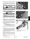
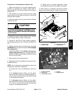
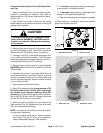
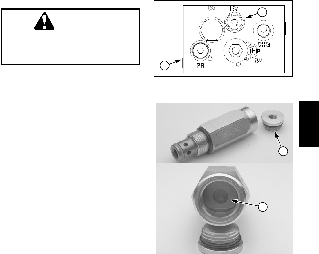
9. Relief valve (RV) is located on the front side of the
4WD manifold (Fig. 35). Adjustment of the relief valve
(RV)canbeperformedasfollows:
NOTE: Do not remove the relief valve from the hydrau-
lic manifold for adjustment.
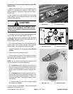
A. Remove cap on relief valve to locate the adjust-
ment socket (Fig. 36). A 1/8 turn on the socket will
makeameasurablechangeinreliefpressure.
B. To increase relief pressure setting, rotate adjust-
ment socket in a clockwise direction.
C. To decrease pressure setting, rotate adjustment
socket in a counterclockwise d irection.
D. Recheck relief pressure and readjust as needed.
10.When testing is completed, disconnect pressure
gauge from manifold test port.
1. 4WD manifold (front) 2. Relief valve (RV)
Figure 35
1
2
Figure 36
1. Relief valve cap 2. Adjustment socket
1
2
Hydraulic
System