


Groundsmaster 4000--D/4010--DPage 7 -- 6Chassis
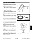
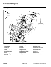
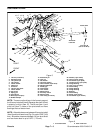
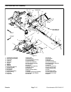
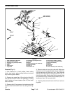
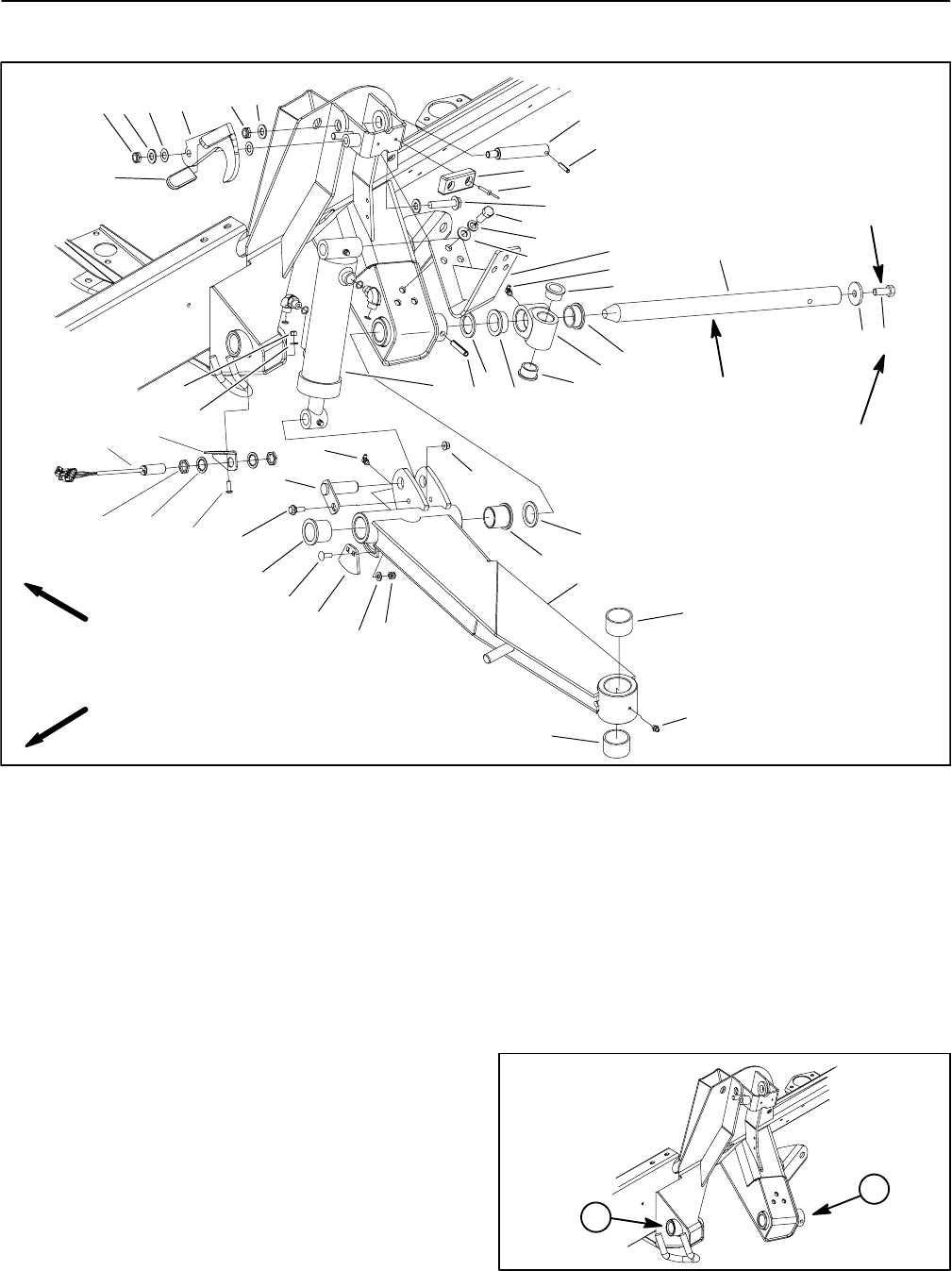
Side Deck Lift Arm
1. Lift arm (LH shown)
2. Shoulder screw
3. Lift cylinder pin
4. Lift cylinder
5. Thrust washer
6. Flange nut
7. Pivot hub
8. Lift arm pivot shaft
9. Thrust washer
10. Cap screw
11. Spring pin
12. Cylinder pin
13. Rivet (2 per bumper)
14. Rubber bumper
15. Slotted roll pin
16. Lock nut
17. Flat washer
18. Latch (LH shown)
19. Thrust washer (2 per latch)
20. Flange head screw
21. Plastic grip
22. Cam bracket
23. Lock washer
24. Switch mount
25. Proximity s witch
26. Sensing plate
27. Lock nut (2 per mount)
28. Washer (2 per switch)
29. Jam nut (2 per switch)
30. Flat washer (2 per plate)
31. Carriage screw (2 per plate)
32. Flange bushing
33. Lock nut (2 per plate)
34. Grease fitting
35. Flange bushing
36. Flange bushing
37. Bushing
38. Grease fitting
39. Screw (2 per mount)
40. Flat washer (2 per mount)
Figure 5
21
16
19
18
16
17
12
11
14
13
3
2
32
4
6
5
1
35
34
7
36
8
9
10
15
5
20
10
17
35
23
26
24
25
28
31
29
30
33
17
27
36
22
34
FRONT
RIGHT
32
37
38
37
Anti--seize
Lubricant
Loctite #242
77 to 96 ft--lb
(105 to 130 N--m)
39
40
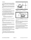
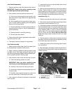
NOTE: There are not bushings in the frame to support
the lift arm pivot shaft (item 8) because the shaft is fixed
in place by a roll pin (item 15). The lift arm (item 1) and
pivot hub (item 7) rotate on the pivot shaft and have
bushings that can be serviced.
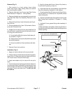
NOTE: Allowableclearance between liftarm pivot shaft
(item 8) and frontframe bore (Fig.6) isupto 0.025” (0.64
mm). Allowable clearance between lift arm pivot shaft
and rear frame bore is up to 0.070” (1.78 mm).
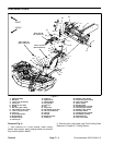
1. Front frame bore 2. Rear frame bore
Figure 6
2
1