


Groundsmaster 4000--D/4010--D Page 7 -- 13 Chassis
Joint Yoke Disassembly
1. Remove retaining rings from yoke and deck mount.
IMPORTANT: Support yoke when removing cross
and bearings to prevent yoke damage.
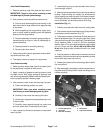
2. Use a press to remove yoke from deck mount:
A. Place a small socket against one bearing in the
deck mount and a large socket on the opposite side
of the mount.
B. While supporting the large socket, apply pres-
sure on small socket to partially push the opposite
bearing into the large socket.
C. Remove assembly from press, grasp partially re-
moved bearing and tap on yoke to completely re-
move the bearing.
D. Repeat process for remaining bearing.
E. Remove yoke from mount.
3. Use a press and the above process to remove bear-
ings and cross from yoke.
4. Thoroughly c lean and inspect all components.
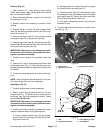
Joint Yoke Assembly
1. Make sure that rubber plate (item 6) and plate (item
5) are positioned in bottom of deck mount.
2. Apply a coating of grease to bearing bores of yoke
and deck mount. Also, apply grease to bearings and
seal of bearing assembly.Make sure thatall bearing roll-
ers are properly seated in bearing cage.
3. Use a press to install cross and bearings into yoke.
A. Press one bearing partially into yoke.
IMPORTANT: Take care when installing cross
into bearing to avoid damaging bearing seal.
B. Carefully insert cross into bearing and yoke.
C. Hold cross in alignment and press bearing in until
it hits the yoke.
D. Carefully place second bearing into yoke bore
and onto cross shaft. Press bearing into yoke.
4. Use a press and the above process to install deck
mount to yoke.
5. Install retaining rings to yoke and deck mount to se-
cure bearings in place.
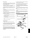
6. Make sure that assembled joint yoke moves without
binding. Slight binding can usually be eliminated by
lightly rapping the yoke lugs with a soft faced hammer.
If binding continues, disassemble joint yoke and deck
mount to identify and eliminate source of binding.
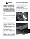
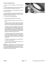
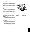
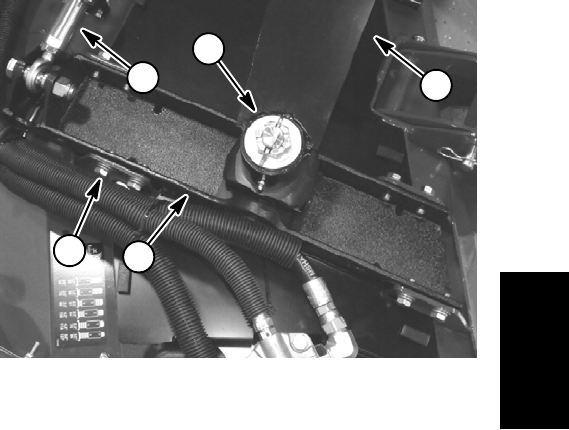
Installation (Fig. 11)
1. Position joint yoke with deck mount to cutting deck.
2. Securedeck mounttodeck with eight(8)capscrews,
lock washers and flat washers (Fig. 12).
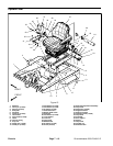
3. Place spacer washer (chamfered ID side down) and
then thrust washer (item 11) onto joint yoke shaft. Insert
yoke shaft up through lift armbushings. Place additional
thrust washers (items 11 and 21) and then hardened
washer (item 12) on yoke shaft and secure with slotted
hex nut. Torque nut from 150 to 180 ft--lb (203 to 244
N--m) while aligning hole in shaft with slot in nut. Install
cotter pin.
4. Position spacers on both sides of rod end ofrear arm
assembly. Secure rod end of rear arm assembly to deck
mount with cap screw and lock nut.
5. Grease jointyoke and lift arm bushings afterinstalla-
tion on machine.
6. After assembly is completed, raise andlower the cut-
ting deck to verify that hydraulichoses andfittings do not
contact anything.
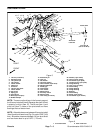
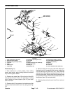
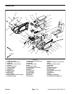
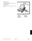
1. Lift arm (RH shown)
2. Joint yoke
3. Rear arm assembly
4. Deck mount
5. Cap screw/washers
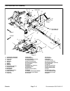
Figure 12
2
1
3
4
5
Chassis