


Groundsmaster 4000--D/4010--D Page 5 -- 25 Electrical System
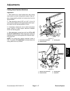
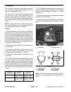
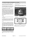
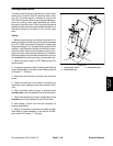
Cutting Deck Lift Switches
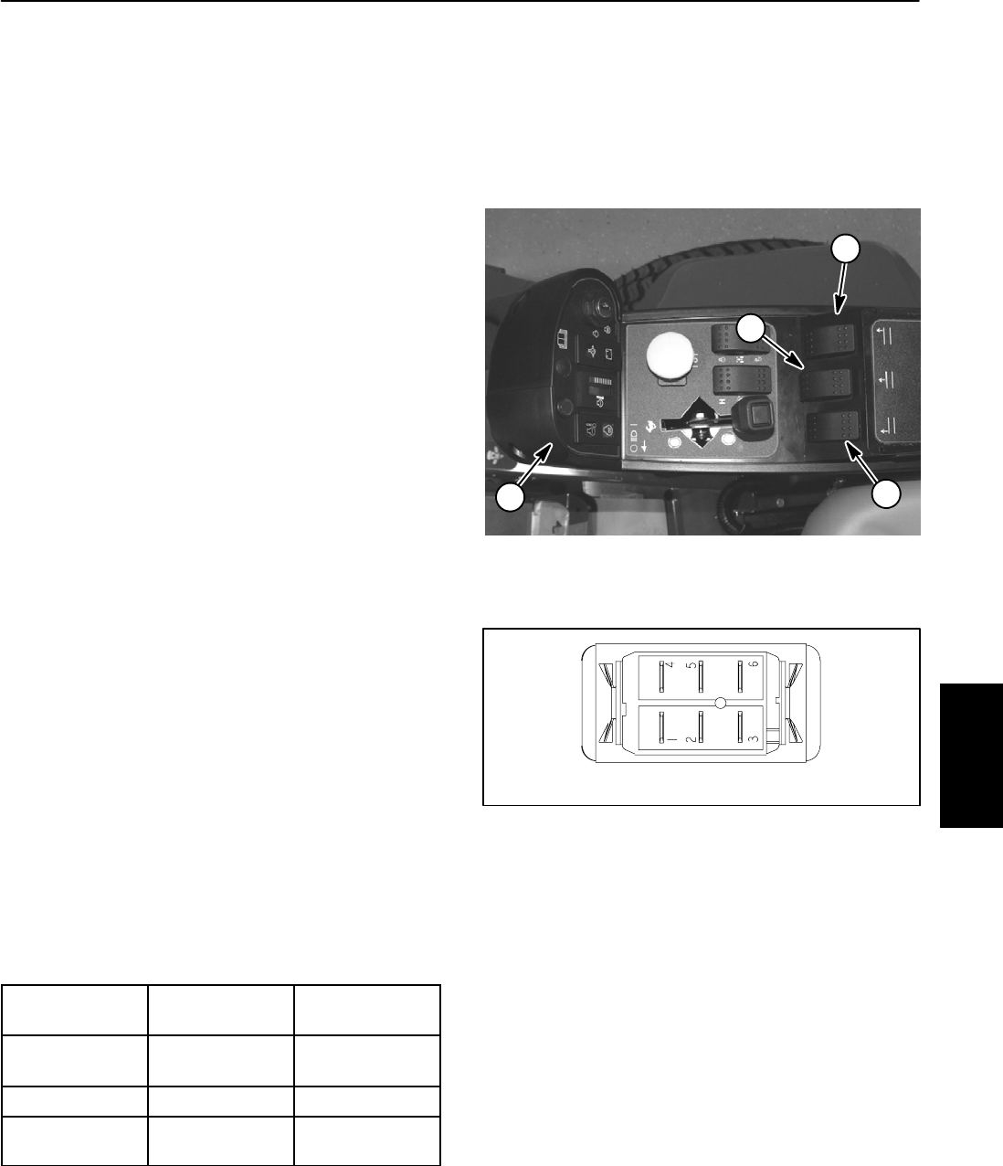
The cutting deck lift switches are used as inputs for the
TEC--5001 controller to raise or lower the cutting decks.
When the front of a lift switch is depressed and held, the
controlled decks will lower. When the rear of a lift switch
is depressed and held, the controlled decks will raise.
The decks will remain in position when the switch is re-
leased. The lift switches are located on the console arm
(Fig. 25).
NOTE: To lower the cutting decks, traction speed has
to be in low range (4WD). Also, to raise or lower the
decks, the operator seat has to be occupied.
Testing
1. Before disconnecting the lift switch for testing, the
switch and its circuit wiring should be tested as a
TEC--5001 input with the Diagnostic Display (see Diag-
nostic Display in the Troubleshooting section of this
chapter). If the Diagnostic Display verifies that the lift
switch and circuit wiringare functioningcorrectly, nofur-
ther switch testing is necessary. If, however, the Display
determines that the lift switch and circuit wiring are not
functioning correctly, proceed with test.
2. Make sure ignition switch is OFF. Remove key from
ignition switch.
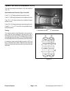
3. Disassemble console arm to gain access to cutting
deck lift switches (see Console Arm Disassembly in the
Service and Repairs section of C hapter 7 -- Chassis).
4. Disconnect harness electrical connector from the lift
switch that is to be tested.
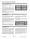
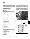
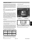
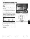
5. The switch terminals are marked as shown in Figure
26. The circuit logic of the lift switches is shown in the
chart below. With the useof amultimeter (ohmssetting),
theswitchfunctionsmay be tested to determine whether
continuity exists between the various terminals for each
position. Verifycontinuity between switch terminals.Re-
place lift switch if testing identifies a faulty switch.
SWITCH
POSITION
CLOSED
CIRCUITS
OPEN
CIRCUITS
DECK LOWER 2+3
5+6
2+1
5+4
NEUTRAL NONE ALL
DECK RAISE 2+1
5+4
2+3
5+6
6. If lift switch tests correctlyand circuit problemstill ex-
ists, check wire harness (see Electrical Schematics and
Wire Harness Drawings in Chapter 10 -- Foldout Draw-
ings).
7. After testing is completed, connect wire harness
connector to the lift switch.
8. Assemble console arm (see Console Arm Assembly
in the Service and Repairs section of Chapter 7 -- Chas-
sis).
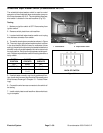
1. Console arm
2. Front deck lift switch
3. RH deck lift switch
4. LH deck lift switch
Figure 25
1
2
3
4
Figure 26
BACK OF SWITCH
NOTE: Lift switch terminals 4, 5 and 6 are not used on
Groundsmaster 4000--D and 4010 --D machines.
Electrical
System