


Groundsmaster 4000--D/4010--D Page 5 -- 37 Electrical System
Testing
1. Park machine on a level surface, lower cutting
decks, stop engine, engage parking brake and remove
key from the ignition switch.
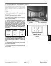
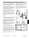
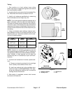
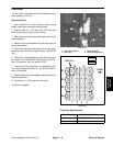
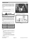
2. Locate hydraulic valve solenoid coil to be tested(Fig.
45). Disconnect wire harness connector from coil.
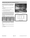
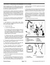
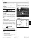
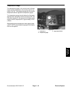
3. Identify coil resistance specification by measuring
the coil diameter and coil height (Fig. 46).
NOTE: Prior to taking small resistance readings with a
digital multimeter, short the meter test leads together.
The meter will display a small resistance value (usually
0.5 ohms or less). This resistance is due to the internal
resistance of the meter and test leads. Subtract this val-
ue from from the measured value of the component you
are testing.
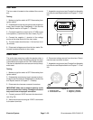
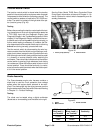
4. Using a multimeter (ohms setting), measure resis-
tance between the two (2) connector terminals on the
solenoid valve coil. The correct resistance for the sole-
noid coil is identified below:
COIL
DIAMETER
COIL
HEIGHT
COIL
RESISTANCE
1.84 in
(46.7 mm)
1.96 in
(49.9 mm)
7.1 ohm
1.41 in
(35.8 mm)
1.43 in
(36.3 mm)
8.8 ohm
NOTE: Solenoid coil resistance should be measured
with solenoid at approximately 68
o
F(20
o
C). Resistance
may be slightly different than listed at different tempera-
tures. Typically, a failed solenoid coil will either be
shorted (very low or no resistance) or open (infinite re-
sistance).
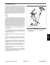
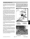
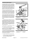
5. If solenoid coil resistance is incorrect, replace sole-
noid:
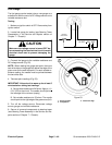
A. Remove nut securing solenoid to the cartridge
valve. Carefully slide solenoid off the valve.
B. Install new solenoid coil to the cartridge valve.
Install and torque nut 5 ft--lb (6.7 N--m). Over--tight-
ening may damage the solenoid coil or cause the
cartridge valve to malfunction.
6. After testing is completed, connect wire harness
connector to the solenoid.
Figure 46
COIL
DIAMETER
COIL
HEIGHT
1. Hydraulic manifold
2. Cartridge valve
3. Solenoid coil
4. Nut
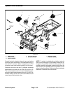
Figure 47
1
2
3
4
5ft--lb
(6.7 N--m)
TRACTION
MANIFOLD SHOWN
Electrical
System