


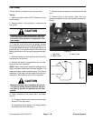
Groundsmaster 4000--D/4010--D Page 5 -- 35 Electrical System
Toro Electronic Controllers (TEC)
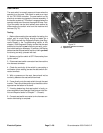
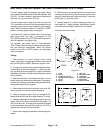
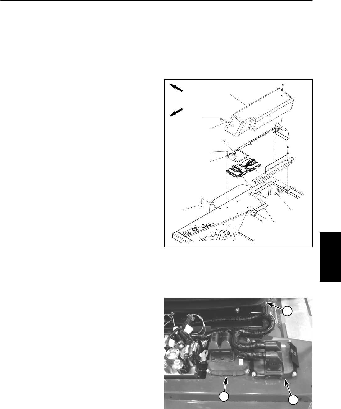
Groundsmaster4000--D and 4010--Dmachinesusetwo
Toro Electronic C ontrollers (TEC) to control electrical
system operation. The controllers are attached to the
operator platform under the controller cover (Figs. 43
and 44).
Logic power is provided to the controllers as long as the
battery cables are connected to the battery. A pair of 2
amp fuses (F3--1 and F4--1) provide circuit protection for
this logic power to the controllers.
The TEC--5002 master controller monitors the states of
the following components as inputs: ignition switch,
parking brake switch, traction neutral switch, seat
switch, engine oil pressure switch, flow divider switch,
Hi/Low speed switch, hydraulic temperaturesender,en-
gine coolant temperature sender, engine cooling fan
switch and optional cruise control switches (if
equipped).
The TEC--5002 controller controls electrical output to
the TEC--5001 controller, hydraulic fan drive manifold
solenoid coils (speed and direction), fuel pump, engine
run solenoid (hold coil), glow plug relay, start relay, high
temperature warning light, diagnostic light, audio alarm,
hydraulic 4WD manifold solenoid coil (flow divider), hy-
draulic traction manifold solenoid coil (Hi/Low speed)
and optional cruise control coil (if equipped). Circuit
protectionforTEC--5002 outputs is provided by three(3)
7.5 amp fuses (F3--2, F3--3 and F3--4).
The TEC--5001 slave controller monitors the states of
the following components as inputs: ignition switch, cut-
ting deck lift switches, PTO switch and deck position
switches.
The TEC--5001 controller controls electrical output to
the hydraulic PTOand lift manifold solenoid coils. Circuit
protectionforTEC--5001 outputs is provided by three(3)
7.5 amp fuses (F4--2, F4--3 and F4--4).
Because of the solid state circuitry built into the TEC
controllers, there is no method to test a controller direct-
ly. A controller may be damaged if an attempt is made
to test it with an electrical test device (e.g. digital multi-
meter or test light).
NOTE: The TEC controllers used on the Groundsmas-
ter 4000 and 4010 are matched for correct machine op-
eration. If either of these components are replaced for
any reason, system software needs to be repro-
grammed by your Toro Distributor.
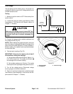
IMPORTANT: Before performing welding on the ma-
chine, disconnect both positive and negative bat-
tery cables from the battery, disconnect wire
harness connector from both of the TEC controllers
and disconnect the terminal connector from the al-
ternator.These steps willprevent damageto the ma-
chine electrical system.
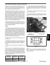
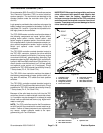
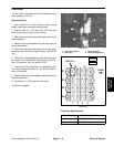
1. Controller cover
2. Screw (2 used)
3. Flat washer (2 used)
4. Flange nut (8 used)
5. Front cover mount
6. Cap screw (8 used)
7. U--nut (2 used)
8. TEC--5001 controller
9. TEC--5002 controller
Figure 43
2
3
6
1
5
4
7
9
8
FRONT
RIGHT
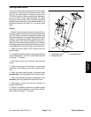
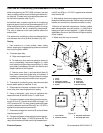
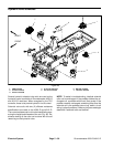
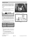
1. TEC--5001 controller
2. TEC--5002 controller
3. Operator seat
Figure 44
1
2
3
Electrical
System