


Groundsmaster 4000--D/4010--D Hydraulic SystemPage 4 -- 81
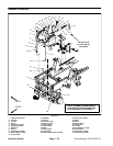
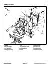
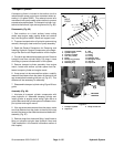
Removal (Fig. 61)
1. Park machine on a level surface, lower cutting
decks, stop engine, apply parking brake and remove
key from the ignition switch.
2. Raise and support machine to gain access to gear
pump from the underside of the machine.
3. Drain the hydraulic reservoir.
4. To prevent contamination of hydraulic system during
removal, thoroughly clean exterior of pump and fittings.
5. Read the General Precautions for Removing and
Installing Hydraulic System Components at the begin-
ning of the Service and Repairs section of this chapter.
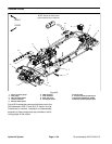
6. Disconnect hydraulic lines from gear pump and put
caps or plugs on open hydraulic lines and fittings. Label
disconnected hydraulic lines for proper installation.
7. Support gear pump assembly to prevent it from fal-
ling.
8. Remove two (2) cap screws and washers securing
gear pump to piston pump. Lower and remove gear
pump, coupler, spacer and O--rings from machine.
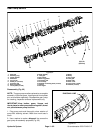
9. If hydraulic fittings are to be removed from gear
pump, mark fitting orientation to allow correct assembly.
Remove fittings from pump and discard O--rings.
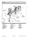
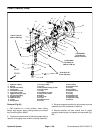
Installation (Fig. 61)
1. If fittings were removed from gear pump, lubricate
and place new O--rings onto fittings. Install fittings into
pump openings using marks made during the removal
process to properly orientate fittings. Tighten fittings
(see Hydraulic Fitting Installation in the General Infor-
mation section of this chapter).
A. If 90
o
hydraulic suction fitting (item 8) was re-
moved, torque fitting nut from 103 to 118 ft--lb (140
to 160 N--m).
2. Lubricate new O--rings (item 13) with clean hydraulic
oil. Position O--rings on gear pump and pump s pacer
flanges.
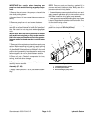
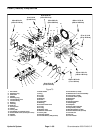
3. Slide coupler onto the piston pump output shaft.
4. Apply Loctite #242 (or equivalent) to threads of cap
screws (item 19) used to secure gear pump to piston
pump.
5. Position pump spacer to gear pump. Aligngear teeth
and slide gear pump input shaft into coupler. Secure
gear pump to piston pump with two (2) cap screws and
flat washers. Torque screws from 79 to 84 ft--lb (108 to
113 N--m).
6. Remove caps and plugs from hydraulic lines and fit-
tings.Using labels placed during pump removal, proper-
ly install lines to gear pump (see Hydraulic Hose and
Tube Installation in the General Information section of
this chapter).
7. Lower machine to ground.
8. Replace hydraulic filter and fill hydraulic reservoir
with new hydraulic oil.
9. Disconnect engine run solenoid electrical connector
to prevent engine from starting. Prime the hydraulic
pump by turning the ignition key switch to start and
crankingtheengine for ten (10) seconds.Letstartercool
and then repeat cranking procedure again.
10.Connect engine run solenoid electrical connector,
start the engine and check for proper operation.
11.Properly fill hydraulic system (see Charge Hydraulic
System in this section).
12.Stop engine and check for hydraulic oil leaks. Check
hydraulic reservoir oil level.
Hydraulic
System