


Groundsmaster 4000--D/4010--DPage 5 -- 44Electrical System
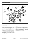
Cutting Deck Position Switches
Three (3) cutting deck position switches are used on the
Groundsmaster 4000--D and 4010--D. These switches
are located on the traction unit frame (Figs. 59 and 60).
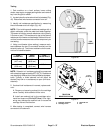
The position switches are powered proximity switches
that incorporate an internal reed switch and a LED. The
deck position switches are used as inputs for the
TEC--5001 controller to prevent deck operation when a
cutting deck is raised. The switch sensing plates are at-
tached to the cutting deck lift arms. The position
switches for front and side decks are different.
The single front cutting deck position s witch is a normal-
ly closed switch. When the front cutting deck is lowered,
the sensing plateon the lift armis awayfrom the position
switch so theswitch is inits normally closedstate. When
the front cutting deck is raised, the sensing plate is
moved near the position switch and the switch opens.
The two (2) side cutting deck position switches are nor-
mally open switches. When a side cutting deck is low-
ered, the sensingplate on the lift arm is near the position
switch and the switch closes. When a s ide cutting deck
is raised, the sensing plate is movedaway from the posi-
tion switch so the switch is in its normally open state.
Testing
1. The cutting deck position switches and their circuit
wiring should be tested as a TEC--5001 input with the
Diagnostic Display (see Diagnostic Display in the Trou-
bleshooting section of this chapter). If the Diagnostic
Display verifies that the position switches and circuit wir-
ing are functioning correctly, no further switch testing is
necessary. If, however, the Display determines that a
positionswitchandcircuit wiring are not functioning cor-
rectly, proceed with test.
2. Park machine on a level surface, lower cutting
decks, stop engine and apply parking brake.
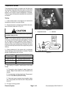
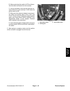
3. Turn ignition switch to the ON position (do not start
engine) and check LED on cable end of position
switches (Fig. 61). Switch LED should be illuminated
when the cutting decks are fully lowered.
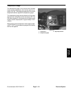
4. Start engine, fully raise cutting decks and then stop
engine. Then, turn ignition switch to the ON position (do
notstartengine) and check LED on cableend ofposition
switches. Switch LED should not be illuminated when
the cutting decks are fully raised.
5. If a position switch LED did not function correctly:
A. Position cutting deck so sensing plate on the lift
arm is near the position switch (front cutting deck
raised and side cutting decks lowered).
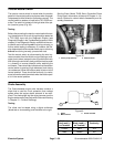
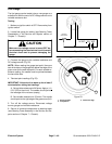
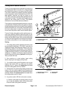
1. Front lift arm (lowered)
2. Position switch
3. Sensing plate
Figure 59
3
1
2
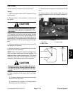
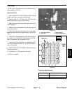
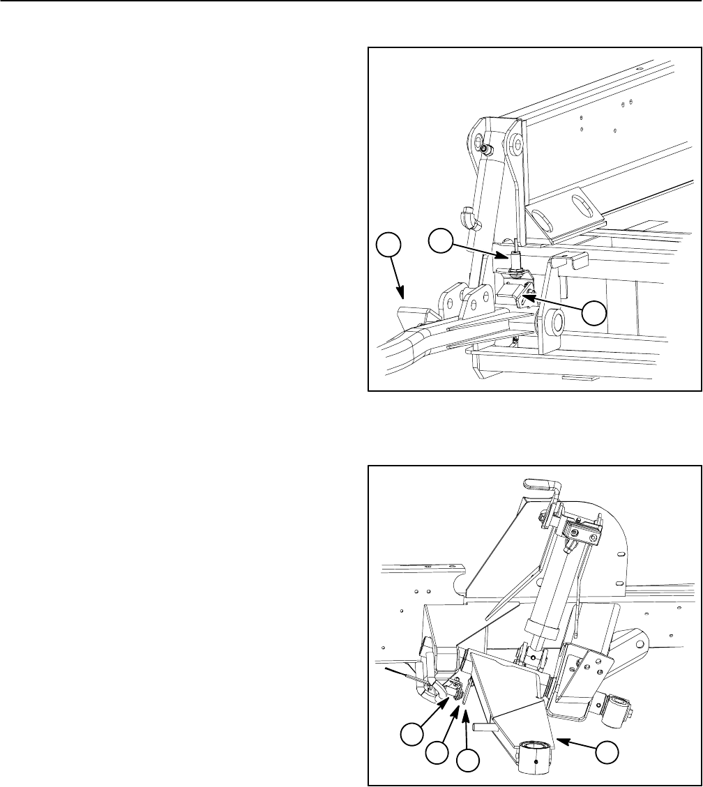
1. Side lift arm (LH shown)
2. Position switch
3. Sensing plate
4. Clearance
Figure 60
3
1
2
4