


Groundsmaster 4000--D/4010--D Hydraulic SystemPage 4 -- 129
Cutting Deck Motor
Removal
1. Park machine on a level surface, lower cutting
decks, stop engine, apply parking brake and remove
key from the ignition switch.
2. Read the General Precautions for Removing and
Installing Hydraulic System Components at the begin-
ning of the Service and Repairs section of this chapter.
3. Thoroughly clean exterior of deck motor and fittings.
Disconnecthydraulic lines from motor.Putcaps or plugs
on fittings and hoses to prevent contamination. Tag hy-
draulic lines for proper installation.
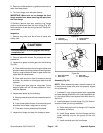
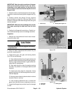
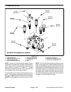
4. Remove two (2) flange head screws that secure hy-
draulic motor to motor mount (Fig. 99).
5. Carefully remove hydraulic motor from cutting deck
taking care not to damage spider hub attached to motor.
Locate and remove spider and mounting shim(s) (if
equipped) from the deck.
6. If necessary, straighten tab washer and remove nut,
tab washer and spider hub from motor shaft.
7. If hydraulic fittings are to be removed from motor,
mark fitting orientation to allow correct assembly. Re-
move fittings from motor and discard O--rings.
Installation
1. If fittings were removed from motor, lubricate and
place new O--rings onto fittings. Install fittings into port
openingsusingmarks madeduringthe removalprocess
to properly orientate fittings. Tighten fittings (see Hy-
draulic Fitting Installation in the General Information
section of this chapter).
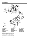
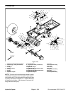
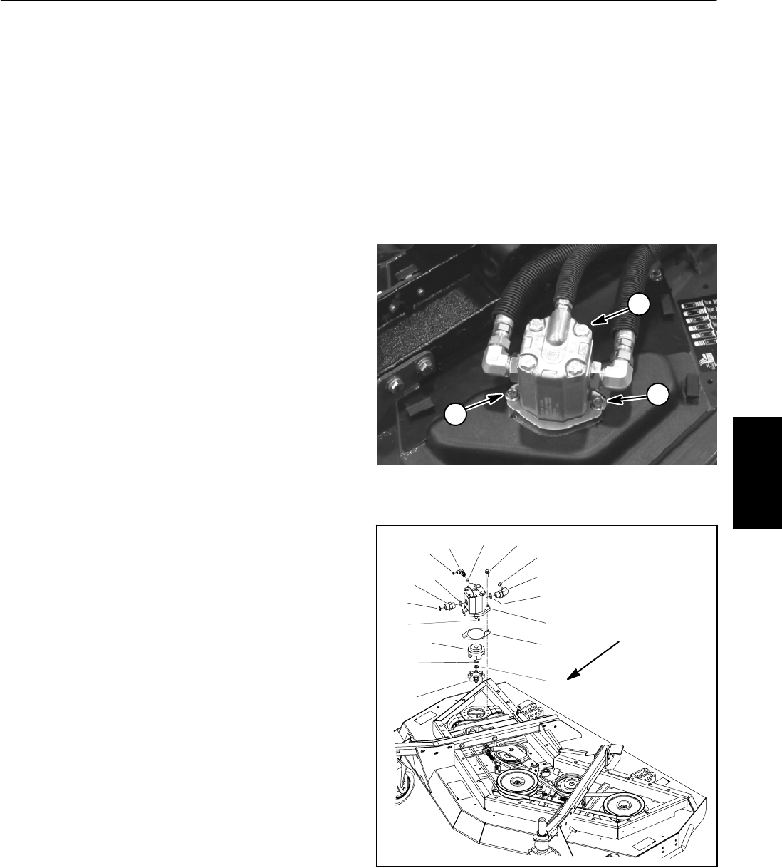
2. If removed, install spider hub on motor shaft. Secure
with tab washer and nut. Torque nut from 27 to 33 ft--lb
(37to44N--m). Bend small tab of washer into keyway
and large tab against nut.
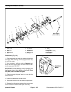
3. Check for proper clearance between spider hub and
spindle pulley. Install motor to cutting deck without plac-
ing the spider in the spindle pulley. The clearance be-
tween hub and pulley valleys should be from 0.830” to
0.930” (21.1 to 23.6 mm). If required, use mounting
shim(s) between motor and motor mount to adjust clea-
rance.
4. Position spider in spindle pulley. Place mounting
shim(s) (if required) on deck. Carefully install hydraulic
motor to the cutting deck taking care not to damage spi-
der hub attached to motor.
5. Secure motor tocutting deck with two(2) flangehead
screws (Fig. 99).
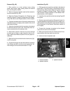
6. Remove caps or plugs from fittings and hoses. Con-
nect hydraulic hoses to deck motor (see Hydraulic Hose
and Tube Installation in the General Information section
of this chapter).
7. After assembly is completed, verify that hydraulic
hoses and fittings are not contacted by moving compo-
nents.
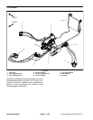
1. Deck motor (RH shown) 2. Flange head screw
Figure 99
1
2
2
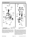
1. Cutting deck motor
2. O--ring
3. Hydraulic adapter
4. O--ring
5. Flange head screw
6. O--ring
7. Hydraulic adapter
8. O--ring
9. 90
o
hydraulic fitting
10. Woodruff key
11. Shim (if required)
12. Spider
13. Nut
14. Tab washer
15. Spider hub
Figure 100
(37to44N--m)
27 to 33 ft--lb
9
12
15
11
2
1
5
7
6
8
3
4
2
4
10
13
14
Hydraulic
System