


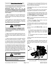
Groundsmaster 4000--D/4010--D Hydraulic SystemPage 4 -- 43
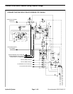
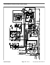
Procedure for Counterbalance Pressure Test
1. Make sure hydraulic oil is at normal operating tem-
perature by operating the machine under load for
approximately ten (10) minutes. Make sure the hydrau-
lic tank is full.
2. Park machine on a level surface with the cutting
decks lowered and off. Make sure engine is off and the
parking brake is applied.
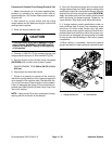
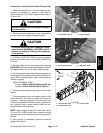
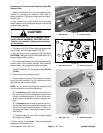
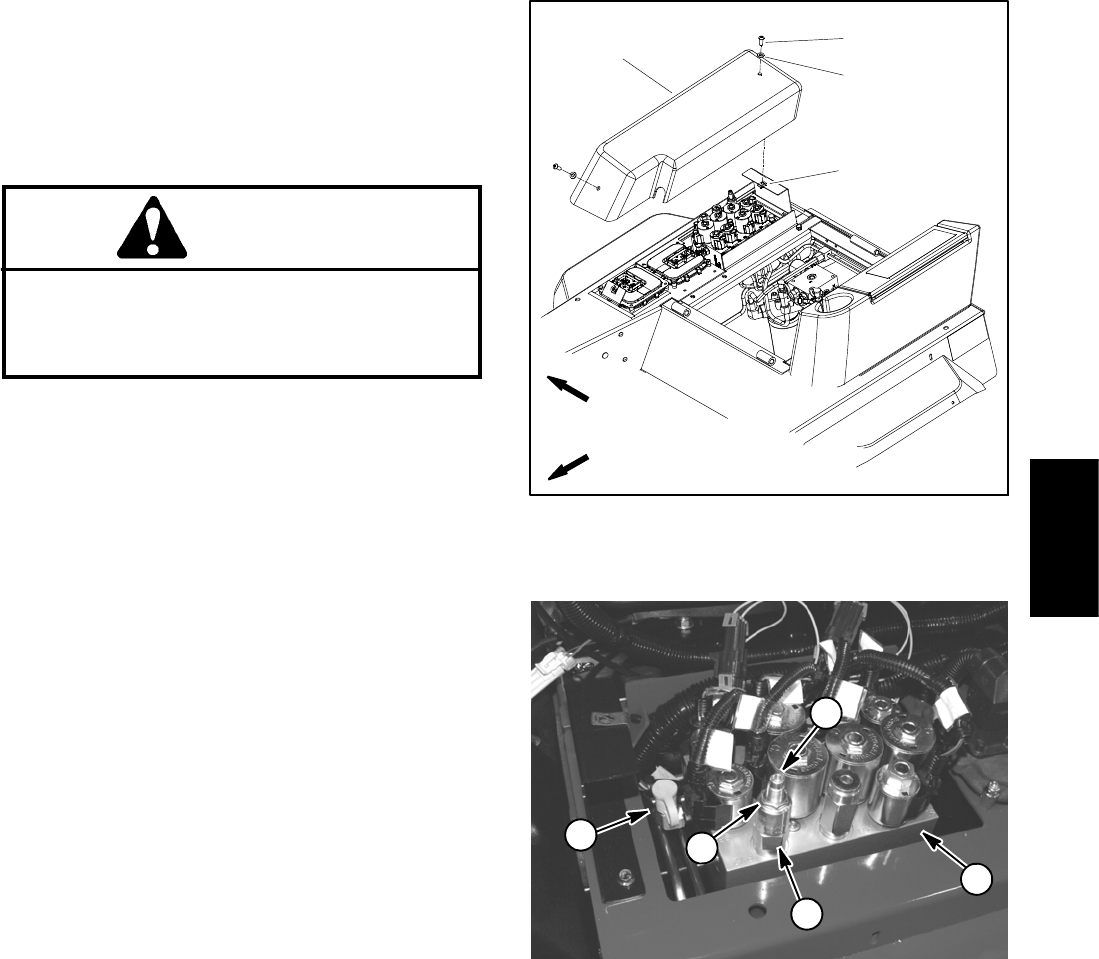
3. Remove controller cover t o gain access to lift/lower
manifold (Fig. 30).
CAUTION
Prevent personal injury and/or damage to equip-
ment. Read all WARNINGS, CAUTIONS and Pre-
cautions for Hydraulic Testing at the beginning
of this section.
4. Determine system charge pressure (see Traction
Circuit Charge Pressure Test in this section).
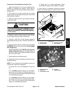
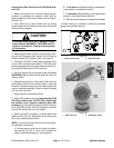
5. Connect a 1000 PSI (70 bar) pressure gauge to
counterbalance test port G2 on lift/lower manifold (Fig.
31).
6. Start the engine and put throttle at high idle speed
(2870 RPM) with no load on the system. Do not engage
the cutting decks.
GAUGE READING TO BE 220 PSI (15.2 bar) over
system charge pressure (e.g. if charge pressure is
250 PSI (17.2 bar), counterbalance pressure should
be 470 PSI (32.4 bar)).
7. Stop engine and record test results.
8. Adjustment of the counterbalance valve can be per-
formed as follows:
NOTE: Do not remove the counterbalance valve from
the hydraulic manifold for adjustment.
A. Loosen lock nut on counterbalance valve (Fig.
31).
B. To increase pressure setting, turn the adjust-
ment screw on the valve in a clockwise direction. A
1/8turnonthescrewwillmakeameasurablechange
in counterbalance pressure.
C. To decrease pressure setting, turn the adjust-
ment screw on the valve in a counterclockwise direc-
tion. A 1/8 turn on the screw will make a measurable
change in counterbalance pressure.
D. Tighten lock nut to secure adjustment. Check
counterbalance pressure and readjust as needed.
9. When testing is completed, disconnect pressure
gauge from manifold test port. Install controller cover.
1. Controller cover
2. Screw (2 used)
3. Flat washer (2 used)
4. U--nut (2 used)
Figure 30
2
3
1
4
FRONT
RIGHT
1. Lift/lower manifold
2. Test port G2
3. Counterbalance valve
4. Lock nut
5. Adjusting screw
Figure 31
2
3
4
5
1
Hydraulic
System