


Groundsmaster 4000--D/4010--D Hydraulic SystemPage 4 -- 149
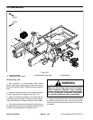
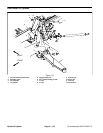
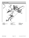
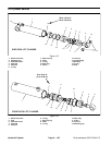
Disassembly (Figs. 115 and 116)
1. Removeoilfromlift cylinder into adrainpan by slowly
pumping the cylinder shaft. Plug both ports and clean
the outside of the cylinder.
IMPORTANT: Prevent damage when clamping the
cylinder in a vise; clamp on the clevis only.
2. Mount lift cylinder securely in a v ise by clamping on
the clevis end of the barrel. Use of a vise with soft jaws
is recommended.
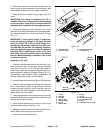
3. Loosen head from barrel:
A. Use a spanner wrench to rotate head clockwise
until theedge of the retaining ring appears in the bar-
rel opening.
B. Insert a screwdriver under the beveled edge of
the retaining ring to start the retaining ring through
the opening.
C. Rotatethe head counter--clockwise to remove re-
taining ring from barrel and head.
4. Extract shaft with head and piston by carefully twist-
ing and pulling on the shaft.
IMPORTANT: Do not clamp vise jaws against the
shaft surface.
5. Mount shaftsecurely in a viseby clampingon thecle-
vis of the shaft. Remove lock nut and piston from the
shaft. Slide head off the shaft.
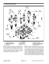
6. Remove and discard all seals and O--rings from the
piston and the head.
7. Wash parts in clean solvent. Dry parts with com-
pressed air. Do not wipe parts dry with paper towels or
cloth. Lint in a hydraulic system will cause damage.
8. Carefully inspect internal surface of barrel for dam-
age(deep scratches,out--of--round,etc.). Inspectpiston
rod and piston for evidence of excessive scoring, pitting
or wear. Replace lift cylinder if internal components are
found to be worn or damaged.
Assembly (Figs. 115 and 116)
1. Make sure all cylinder components are clean before
assembly.
2. Coat new seal kit components with clean hydraulic
oil.
A. Install new seals and O--rings to the piston.
B. Install new seals, O--ring and back--up ring to the
head.
IMPORTANT: Do not clamp vise jaws against the
shaft surface.
3. Mount shaftsecurely in a viseby clampingon thecle-
vis of the shaft.
A. Coat shaft with clean hydraulic oil.
B. Carefully slide head and piston onto the shaft.
Secure piston to shaft with lock nut.
C. Torque lock nut to specification in Figure 115
(side deck cylinder) or Figure 116 (front deck cylin-
der).
4. Lubricate head and piston with clean hydraulic oil.
Carefully slide shaft assembly into cylinder barrel.
IMPORTANT: Prevent damage when clamping the
cylinder’s barrel into a vise; clamp on the clevis
only.
5. Mount lift cylinder in a vise with soft jaws. Secure
head in barrel:
A. Align retaining ring hole in the head with the ac-
cess slot in the barrel.
B. Insert the retaining ring hook into the hole and ro-
tate head clockwise until the retaining ring is com-
pletely pulled into the barrel and the ring ends are
covered.
C. Apply silicone sealer to barrel access slot.
Hydraulic
System