


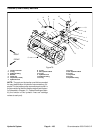

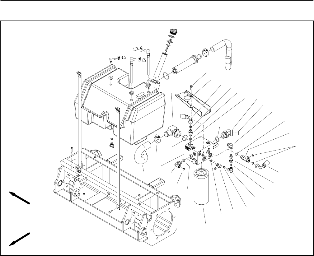
Groundsmaster 4000--D/4010--DHydraulic System Page 4 -- 104
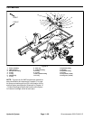
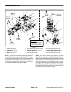
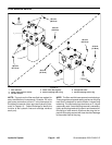
Filter Manifold
1. Filter manifold
2. 45
o
hydraulic fitting
3. Test nipple
4. Dust cap
5. O--ring
6. O--ring
7. O--ring
8. Cap screw (3 used)
9. Flat washer (3 used)
10. Hydraulic fitting
11. O--ring
12. O--ring
13. 90
o
hydraulic fitting
14. Hydraulic hose
15. O--ring
16. O--ring
17. 90
o
hydraulic fitting
18. Hydraulic hose
19. Hydraulic tee fitting
20. 90
o
hydraulic fitting
21. O--ring
22. Hose clamp
23. Hydraulic hose
24. Barb fitting
25. Oil filter
Figure 78
FRONT
RIGHT
13
10
8
9
19
1
17
2
3
20
23
18
14
4
21
16
12
15
7
11
5
6
22
24
25
6
11
11
6
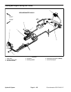
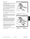
NOTE: The ports on the filter manifold are marked for
easy identification of components. Example: P2 is the
gear pump connection port and T is the connection for
the hydraulic reservoir return port (see Hydraulic Sche-
matic in Chapter 10 -- Foldout Drawings to identify the
function of the hydraulic lines and cartridge valves at
each port).