


Groundsmaster 4000--D/4010--DHydraulic System Page 4 -- 106
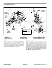
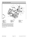
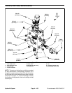
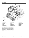
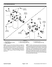
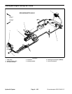
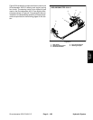
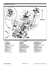
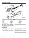
Filter Manifold Service
1. Filter manifold
2. Check valve (reservoir return)
3. Oil filter element
4. Check valve (filter bypass)
5. #6 zero leak plug with O--ring
6. Charge relief valve
7. #8 zero leak plug with O--ring
Figure 79
FRONT
UP
6
7
1
5
5
4
2
FRONT
UP
3
3
25 ft--lb
(34 N--m)
30 ft--lb
(41 N--m)
50 ft--lb
(67 N--m)
25 ft--lb
(34 N--m)
25 ft--lb
(34 N--m)
30 ft--lb
(41 N--m)
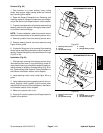
NOTE: The ports on the filter manifold are marked for
easy identification of components. Example: P2 is the
gear pump connection port and T is the connection for
the hydraulic reservoir return port (see Hydraulic Sche-
matic in Chapter 10 -- Foldout Drawings to identify the
function of the hydraulic lines and cartridge valves at
each port).
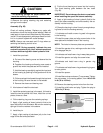
NOTE: Thefilter manifolduses several zero leakplugs.
These plugs have a tapered sealing surface on the plug
head that is designed to resist vibration induced plug
loosening. The zero leak plugs also have an O --ring as
asecondaryseal.If zero leak plug removal isnecessary,
lightly rap the plug head using a punch and hammer be-
fore using an allen wrench to remove the plug: the im-
pact will allow plug removal with less chance of damage
to the socket head of the plug.