


Groundsmaster 4000--D/4010--D Hydraulic SystemPage 4 -- 125
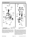
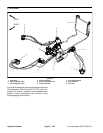
Removal (Fig. 95)
1. Park machine on a level surface, lower cutting
decks, stop engine, apply parking brake and remove
key from the ignition switch.
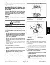
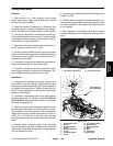
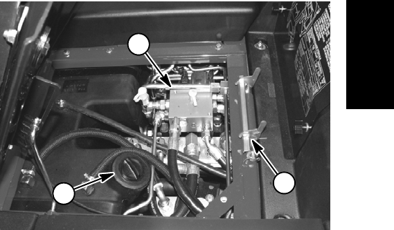
2. Raise and support operator seat to allow access to
fan drive manifold (Fig. 96).
3. Read the General Precautions for Removing and
Installing Hydraulic System Components at the begin-
ning of the Service and Repairs section of this chapter.
4. To prevent contamination of hydraulic system during
manifold removal, thoroughly clean exterior of fan drive
manifold and fittings.
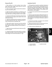
5. Label wire harness electrical connectors that attach
to manifold solenoid valve coils. Disconnect wire har-
ness connectors from the solenoid coils.
6. Disconnect hydraulic lines from fan drive manifold
and put caps or plugs on open hydraulic lines and fit-
tings. Label disconnected hydraulic lines for proper re-
assembly.
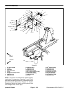
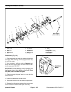
7. Remove fan drive manifold fromthe frame using Fig-
ure 95 as a guide.
8. If hydraulic fittings are to be removed from manifold,
mark fitting orientation to allow correct assembly. Re-
move fittings from manifold and discard O--rings.
Installation (Fig. 95)
1. If fittings were removed from manifold, lubricate and
place new O--rings onto fittings. Install fittings into man-
ifold openings using marks made during the removal
process to properly orientate fittings. Tighten fittings
(see Hydraulic Fitting Installation in the General Infor-
mation section of this chapter).
2. Install fan drive manifold tothe frameusing Figure 95
as a guide.
3. Remove caps and plugs from fittings and hoses. Us-
ing labels placed during manifold removal, properly con-
necthydraulic lines to manifold (see Hydraulic Hose and
Tube Installation in the General Information section of
this chapter).
4. Connect wire harness connectors to the solenoid
valve coils on the fan drive manifold.
5. Make sure hydraulic tankis full. Add correctoil if nec-
essary before returning machine to service.
6. Lower and secure operator seat.
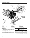
1. Fan drive manifold
2. Hydraulic reservoir
3. Operator seat latch
Figure 96
2
1
3
Hydraulic
System