


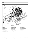
Groundsmaster 4000--D/4010--DPage 3 -- 16Kubota Diesel Engine
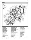
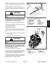
7. Install fan motor and fan assembly (Fig. 15).
A. Carefullyposition fan motor,fanand motor brack-
et assembly to radiator.
B. Secure fan motor bracket to radiator with six (6)
cap screws and flange nuts.
C. Remove caps and plugs placed in hoses and fit-
tings during removal to prevent contamination.
D. Connect hydraulic hoses to cooling fan motor
(see Hydraulic Hose and Tube Installation in the
General Information section of Chapter 4 -- Hydraulic
System).
8. Position upper radiator shroud and coolant reservoir
with brackettotheradiator.Secure shroud and reservoir
bracket to the radiator and lower radiator bracket with
removed fasteners (seeRadiator Installation in this sec-
tion). Make sure that clearance between shroud and fan
is at least 0.180” (4.6 mm) at all points.
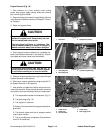
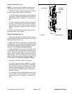
9. Connect throttle cable to injector pump (Figs. 13 and
14):
A. Secure throttle cable swivel to speed control le-
ver with lock nut.
B. Place throttle cable under cable clamp.
C. Adjust throttle cable position in cable clamp so
that engine governor lever contacts the high speed
stop bolt at the same time that the throttle lever con-
tacts the end of the slot in the control console.
D. Tighten cable clamp to secure throttle cable.
10.Connect fuel line to the injection pump (Fig. 13).
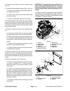
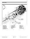
11.Install transport cylinder assembly to engine adapter
plate (Fig. 16). Make sure that cylinder spacer is posi-
tioned between transport cylinder and engine mount.
12.On Groundsmaster 4010--D machines:
A. Position windshield washer reservoir to bracket
on engine (Fig. 17). Secure with removed fasteners.
B. Install air conditioning compressor to brackets
(see Air Conditioning Compressor Installation in the
Service and Repairs sectionof C hapter 9 -- Operator
Cab).Makesurethatdrive belt is properly tensioned.
C. Connect coolant hose to fitting on engine water
flange.
13.Connect wires and/or electrical connections to the
following electrical components:
A. The temperature sender and alternator (Fig 11).
B. The glow plug (Fig. 12).
C. The engine run solenoid.
D. Battery, frame and wireharness groundtothe en-
gine block.
E. The starter and low oil pressure switch (near
starter).
F. The air conditioning compressor (Groundsmas-
ter 4010--D machines).
14.Install aircleaner assembly to theengine(see Air Fil-
ter System Installation in this section).
15.Install exhaustsystemtomachine (see ExhaustSys-
tem Installation in this section).
16.Connect coolant hoses to the radiator.Make sure ra-
diator drain is shut. Fill radiator and reservoir with cool-
ant.
17.Check position of wires, fuel lines, hydraulic hoses
and cables for proper clearance with rotating, high tem-
perature and moving components.
18.Install battery to machine (see Battery Service in the
Service and Repairs section of Chapter 5 -- Electrical
System). Make sure to connect positive battery cable
first and then negative battery cable. Secure battery to
machine with strap and cover.
19.Check and adjust engine oil as needed.
20.Check and adjust hydraulic oil as needed.
21.Bleed fuel system.
22.Start engine and operate hydraulic controls to prop-
erly fill hydraulic system (see Charge Hydraulic System
in the Service and Repairs section of Chapter 4 -- Hy-
draulic System).
23.Close and secure hood.