


Groundsmaster 4000--D/4010--D Hydraulic SystemPage 4 -- 77
NOTE: The front frame needs to be lowered from the
main frame to allow clearance to remove the hydraulic
reservoir from the machine.
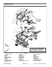
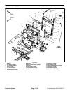
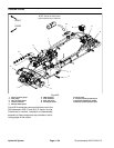
Removal (Fig. 59)
1. Park machine on a level surface, lower cutting
decks, stop engine, apply parking brake and remove
key from the ignition switch.
2. Remove front cutting deck (see Front Cutting Deck
Removal in the Service and Repairs section of Chapter
8 -- Cutting Decks).
3. Read the General Precautions for Removing and
Installing Hydraulic System Components at the begin-
ning of the Service and Repairs section of this chapter.
4. Drain reservoir into a suitable container.
5. Disconnect hydraulic hoses from reservoir. Label
disconnected hydraulic lines for proper installation.
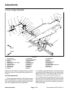
6. Remove straps (items 4 and 8) that secure reservoir
to frontframe. Remove felt straps (item 5) from between
straps and reservoir.
7. To allow front frame to be lowered for reservoir re-
moval, remove hydraulic tubes that connect hydraulic
components on front frame (wheel motors, front deck
PTO manifold and traction manifold) to components on
main frame. Put caps or plugs on open hydraulic lines
and fittings.
8. Chockrearwheelstoprevent the machine frommov-
ing. Use jack or hoist to raise front of machine and sup-
port machine with jackstands.
9. Support front frame to prevent it from moving.
10.Remove capscrews (item 31),flat washers (item28)
and flangenuts ( item 30) that secure front frame to main
frame.
11.Carefully lower front frame assembly to allow clear-
ance for reservoir removal. Once lowered, support front
frame to prevent it from shifting.
12.Carefully remove hydraulic reservoir from machine.
Inspection
1. Clean hydraulic reservoir and suction strainer with
solvent.
2. Inspect reservoir for leaks, cracks or other damage.
Installation (Fig. 59)
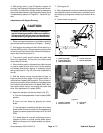
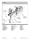
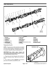
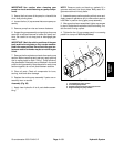
1. Using a wrench, turn tank strainer into port at least
1--1/2 to 2 full turns beyond finger tight.
2. Position reservoir to machine.
3. Carefully raise front frame assembly to main frame.
Align frame mounting holes and support front frame to
prevent it from moving.
4. Secure front frame to main frame with cap screws
(item 31), flat washers (item 28) and flange nuts (item
30). Tighten two (2) fasteners at rear of frame before
tightening top four (4) fasteners.
5. Lower machine to ground.
6. Position felt straps (item 5) between straps and res-
ervoir. Secure reservoir to front frame with straps (items
4 and 8).
7. Remove caps and plugs from hydraulic lines and fit-
tings that were placed during the removal process. Us-
ing labels placed during reservoir removal, connect
hydraulic hoses and tubes to fittings on reservoir, wheel
motors and hydraulic manifolds (see Hydraulic Hose
and Tube Installation in the General Information section
of this chapter).
8. Install front cutting deck (see Front Cutting Deck
Installation in the Service and Repairs section of Chap-
ter 8 -- Cutting Decks).
9. Fill reservoir with new hydraulic fluid to proper level.
10.Properly fill hydraulic system (see Charge Hydraulic
System in this section).
11.Stop engine and check for hydraulic oil leaks. Check
hydraulic reservoir oil level.
Hydraulic
System