


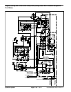
Groundsmaster 4000--D/4010--D Hydraulic SystemPage 4 -- 71
4. With ignition switch in the ON position (engine not
running), use Diagnostic Display to make sure that neu-
tral switch is closed when traction pedal is released to
theneutraldetentposition (see Diagnostic Display in the
Troubleshooting section of Chapter 5 -- Electrical Sys-
tem).
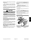
Adjustments with Engine Running
CAUTION
All wheels willbe offthe ground androtatingdur-
ing the following procedure. Make sure machine
is supported so it will not move and accidentally
fall to prevent injuring anyone near the machine.
1. Raise and support machine so all wheels are off the
ground (see Jacking Instructions in Chapter 1 -- Safety).
2. Start engine and make sure that Hi/Low switch is in
the Low (4WD) position. Depress traction pedal to allow
oil flow through thetraction circuit.Allow allwheels to ro-
tate to warm up the hydraulic oil.
3. The traction pedal should contact the pedal stop
when fully depressed. At this point, the piston pump
should be at full stroke.
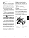
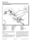
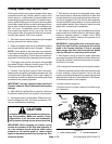
4. When traction pedal is released from either forward
or reverse, pedal should return to the neutral position
and wheels should stop rotating. If necessary, adjust
spring shaft (item 5 in Fig. 56) until neutral operation is
correct.
5. With the engine running, the transport cylinder on
engine should extend when Hi/Low speed switch is
moved to the Hi speed (2WD) position. This cylinder ex-
tension prevents the piston (traction) pump swash plate
from reaching full stroke when in Hi speed (2WD). Also,
the traction pedal should not contact the pedal stop
when fully depressed in Hi speed (2WD).
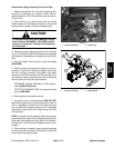
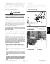
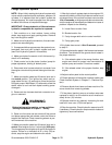
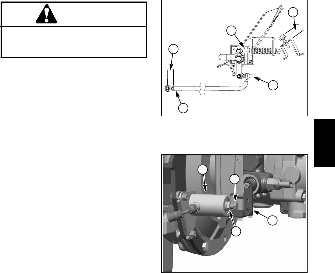
6. Adjust the transport cylinder as follows (Fig. 57):
A. PlaceHi/Lowspeed switch in the Hi speed(2WD)
position.
B. Lock one front wheel by applying the wheel
brake.
C. Use a phototac to measure the other front wheel
speed. When the traction pedal is fully depressed to
forward, the wheel speed should be from 370 to 422
RPM.
D. If wheel speed is incorrect, adjust c ap screw in
transport cylinder to provide correct wheel speed.
Make sure that jam nut is tightened after any adjust-
ment.
7. Shut engine off.
8. After adjustments have been made and all fasteners
are tightened, make sure that traction rod does not con-
tact anything through both forward and reverse direc-
tions.
9. Lower machine to ground.
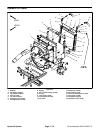
1. Pedal stop height
2. Traction pump end
3. Rod end dimension
4. Traction lever end
5. Neutral adjustment
Figure 56
1
2
3
4
5
1. Transport cylinder
2. Pump control arm
3. Cap screw
4. Jam nut
Figure 57
1
3
2
4
Hydraulic
System