


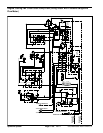
Groundsmaster 4000--D/4010--D Hydraulic SystemPage 4 -- 67
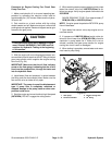
Procedure for Engine Cooling Fan Circuit Test
1. Make sure hydraulic oil is at normal operating tem-
perature by operating the machine under load for
approximately ten (10) minutes. Make sure the hydrau-
lic tank is full.
2. Park machine on a level surface with the cutting
decks lowered and off. Make sure engine is off and the
parking brake is applied. Raise and support hood.
CAUTION
Prevent personal injury and/or damage to equip-
ment. Read all WARNINGS, CAUTIONS and Pre-
cautions for Hydraulic Testing at the beginning
of this section.
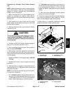
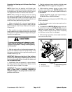
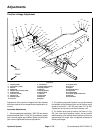
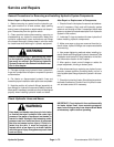
3. Raise seat to gain access to the fan drive manifold
(Fig. 51). Connecta 5,000 PSI (345 bar) pressuregauge
with hydraulic hose attached to test port on top of man-
ifold.
4. Start the engine. Move throttle to high idle speed
(2870 RPM).
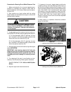
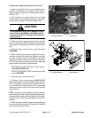
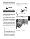
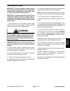
5. While monitoring the pressure gauge and using a
phototac to identify the cooling fan speed, disconnect
the wire harness connector (white/green and black
wires) from the PRV solenoid on fan drive manifold (Fig.
52). Both fan speed and pressure should increase and
stabilize after the solenoid is disconnected.
PRESSURE GAUGE READING TO BE approxi-
mately 3000 PSI (207 bar).
PHOTOTAC READING TO BE: fan speed should be
at least 2800 RPM.
6. Stop engine and record test results.
7. If pressure rises to approximately 3000 PSI (207
bar) but fan speed is low, consider that the fan motor is
worn or damaged. If pressure and fan speed are both
low, consider that the gear pump is worn or damaged
(see Engine Cooling Fan Circuit Gear Pump Flow Test
in this section).
NOTE: If pressure and fan speed are both low and gear
pump flow proves to be correct, suspect that seals in fan
drive manifold are leaking or faulty (see Fan Drive Man-
ifold Service in the Service and Repairs section of this
chapter).
8. When testing is complete, remove pressure gauge
and reconnect wire harness to PRV solenoid. Lower and
secure hood and operator seat.
1. Fan drive manifold 2. Test port G1
Figure 51
1
2
1. Fan drive manifold 2. PRV solenoid
Figure 52
1
2
Hydraulic
System