


Rev. AGroundsmaster 4000--D/4010--D Page 3 -- 7 Kubota Diesel Engine
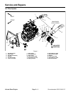
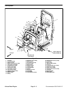
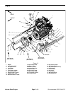
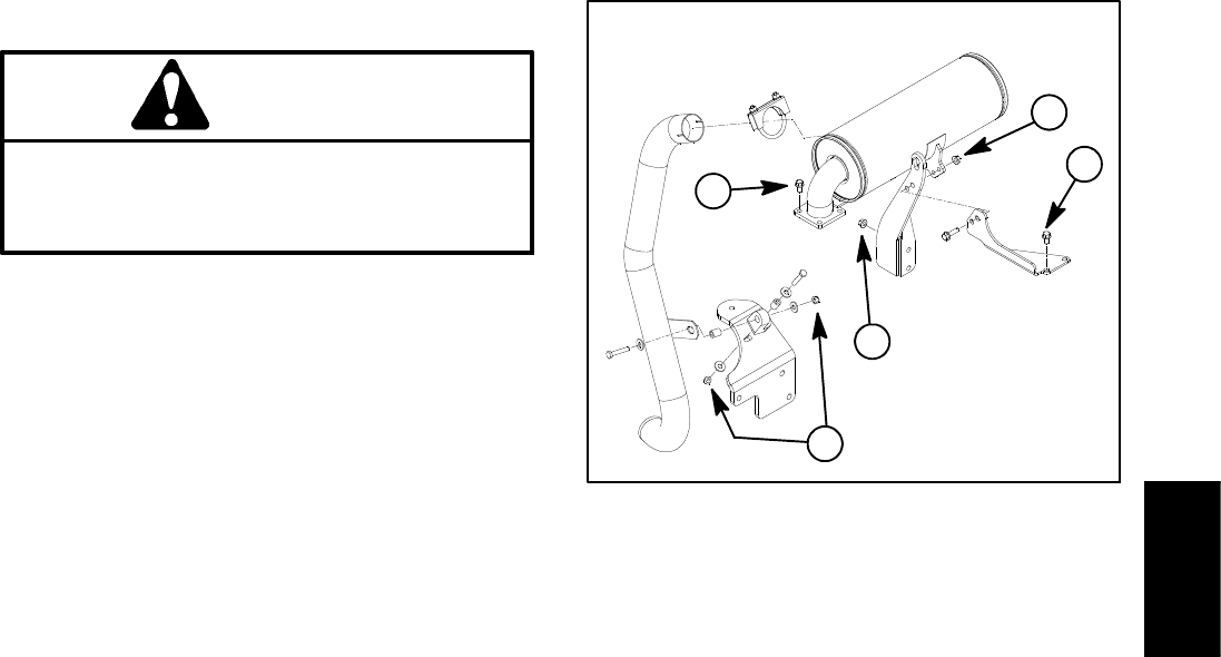
Removal (Fig. 5)
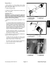
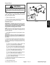
CAUTION
The muffler and exhaust pipe may be hot. To
avoid possible burns, a llow the engine and ex-
haust system to cool before working on the muf-
fler.
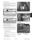
1. Park machine on a level surface, lower cutting
decks, stop engine, apply parking brake and remove
key from the ignition switch.
2. Raise and support hood.
3. Remove exhaust system components from the en-
gine as necessary using Figure 5 as a guide.
Installation (Fig. 5)
IMPORTANT: If exhaust studs were removed from
engine cylinder head, thoroughly clean threads in
head and apply Loctite #277 (o r equivalent) to stud
threads before installing studs into head.
NOTE: Make sure muffler flange and exhaust manifold
sealing surfaces are free of debris or damage that may
prevent a tight seal.
1. Install new exhaust gasket if original gasket is dam-
aged or torn.
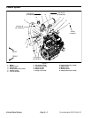
IMPORTANT: Failure to follow the suggested muf-
fler fastener sequence may result in premature muf-
fler failure.
2. Install exhaust system components to the engine us-
ing Figure 5 as a guide. Hand tighten exhaust system
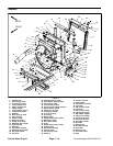
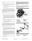
fasteners and then torque in the sequence shown in Fig.
6 a s follows:
A. Torque lock nuts used on rubber hanger cap
screws from 16 to 22 ft--lb (21 to 29 N--m).
B. Torque flange head screws that secure muffler
flange to engine from 16 to 22 ft--lb (21 to 29 N--m).
C. Torque flange nuts that secure muffler to muffler
bracket from 16 to 22 ft--lb (21 to 29 N--m).
D. Torque flange nuts that secure muffler bracket to
engine from 16 to 22 ft--lb (21 to 29 N--m).
E. Torque flange screws that secure exhaust mount
to engine to 1 3 f t -- l b ( 1 7 . 6 N -- m ) .
3. Tailpipe should have equal clearance between frame
and engine after installation.
4. Lower and secure hood.
Figure 6
C
D
B
A
E
Kubota
Diesel Engine