


Groundsmaster 4000--D/4010--D Page 5 -- 45 Electrical System
B. Make sure that ignition switch is OFF and discon-
nect the switch connector from wire harness.
C. Using a multimeter, verify that wire harness con-
nector terminal for pink wire has 12 VDC when the
ignition switch is ON.
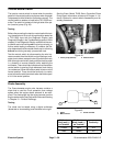
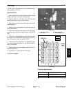
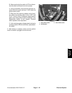
D. Make sure that clearance between end of posi-
tion switch and sensing plate is from 0.070” and
0.130” (1.8 to 3.3 mm). If necessary, adjust position
switch (see Cutting Deck Position Switches in the
Adjustments section of this chapter). Recheck
switch operation after adjustment.
E. Ifpink wirehas system voltage present and gap is
correct but switch LED did notfunction, replace posi-
tion switch.
6. After testing is complete, make sure that position
switch connector is plugged into wire harness.
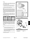
1. Side position switch
2. Sensing plate
3. Switch LED location
Figure 61
2
1
3
Electrical
System