


Groundsmaster 4000--D/4010--D Hydraulic SystemPage 4 -- 23
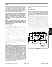
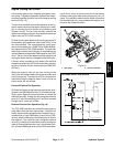
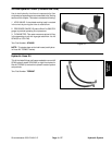
Steering Circuit
A four section gear pump is coupled to the piston (trac-
tion) pump. The third gear pump section supplies hy-
draulic flow to both the steering and lift/lower circuits.
Hydraulic flow from this pump section is delivered to the
two circuits through a proportional flow divider that is lo-
cated in the fan drive manifold. This flow divider splits
pump flow approximately 50% for the steering circuit
and 50% for the lift/lower circuit.
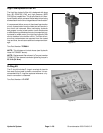
Steering circuit pressure is limited to 1350 PSI (93 bar)
by a relief valve located in the steering control valve. Cir-
cuit pressure can be measured at a test port in the hy-
draulic supply tube.
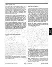
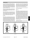
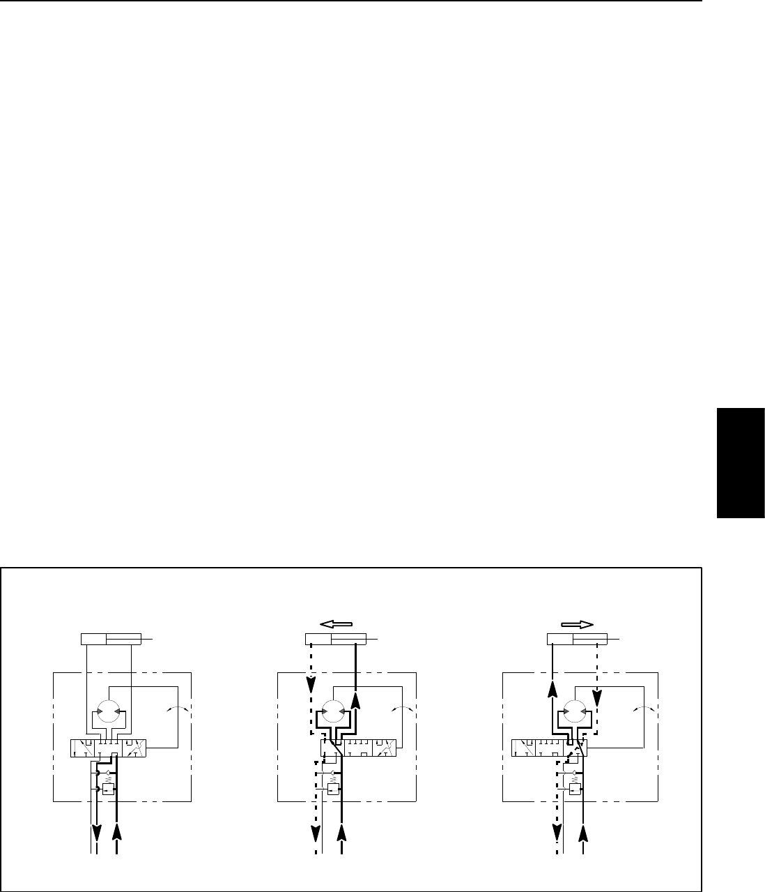
With the steering wheel in the neutral position and the
engine running, flow enters the steering control valve at
the P port and goes through the steering control spool
valve, by--passing the rotary meter (V1) and steering
cylinder. Flow leaves the control valve through the PB
port to the oil filter and traction charge circuit.
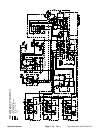
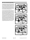
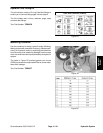
Left Turn
When a left turn is made with the engine running, the
turning ofthe steering wheel positions the spool valve so
that flow goes through the top of thespool. Flowentering
the steering control valve at the P port goes through the
spool and is routed to two places. First, most of the flow
throughthevalveisby--passedoutthePBportbackto
the oil filter and traction charge circuit. Second, the re-
mainder of the flow is drawn through the rotary meter
(V1) and out the L port. Pressure retracts the steering
cylinder piston for a left turn. The rotary meter ensures
that the oil flow to the cylinder is proportional to the
amount of the turning on the steering wheel. Fluid leav-
ing the cylinder flows back through the spool valve then
through the T port and to the hydraulic reservoir.
The steering control valve returns to the neutral position
when turning is completed.
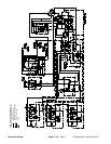
Right Turn
When a right turn is made with the engine running, the
turning of the steering wheel positions the spool valve so
that flow goes through the bottom of the spool. Flow en-
tering the steering control valve at the P port goes
through the spool and is routed to two places. As in a left
turn, most of the flow through the valve is by--passed out
the PB port back to the oil filter and traction charge cir-
cuit. Also like a left turn, the remainder of the flow is
drawn through rotary meter (V1) but goes out port R.
Pressure extends the steering cylinder p iston for a right
turn. The rotary meter ensures that the oil flow to the cyl-
inder is proportional to the amount of the turning on the
steering wheel. Fluid leaving the cylinder flows back
through the spool valve then through the T port and to
the hydraulic reservoir.
The steering control valve returns to the neutral position
when turning is completed.
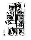
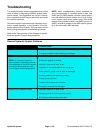
Figure 14
1350
PSI
PB
STEERING
T
R
P
L
PISTON MOVEMENT
CONTROL
1350
PSI
PB
STEERINGCYLINDER
STEERING
T
R
P
L
PISTONMOVEMENT
CONTROL
1350
PSI
PB
STEERINGCYLINDER
STEERING
T
R
P
L
CONTROL
LEFT TURN
NEUTRAL POSITION
RIGHT TURN
NOPISTONMOVEMENT
STEERINGCYLINDER
Hydraulic
System