


Groundsmaster 4000--D/4010--D Page 5 -- 39 Electrical System
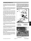
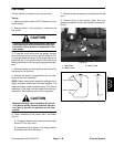
Fuel Sender
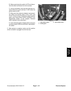
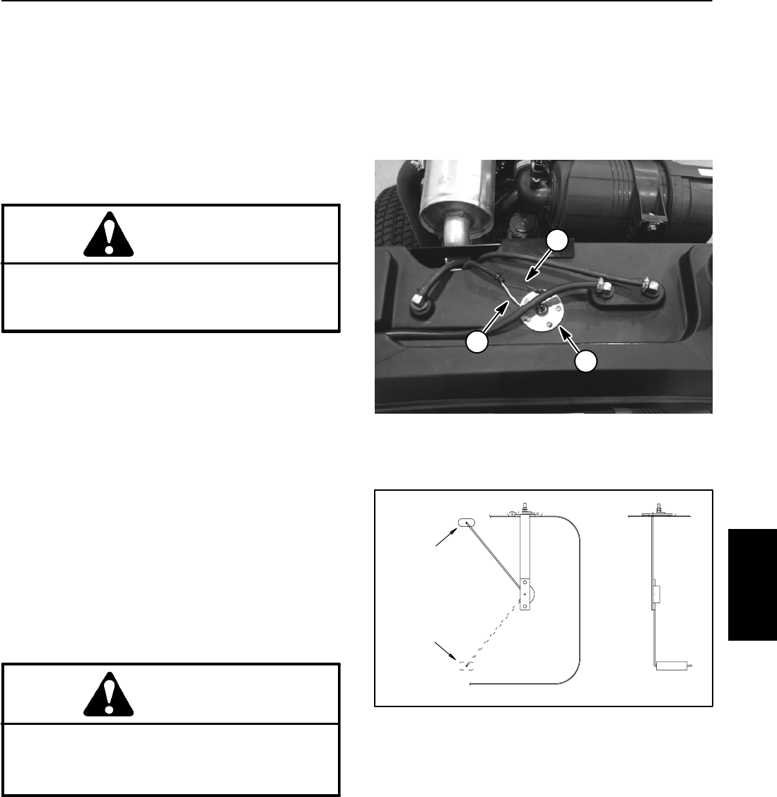
The fuel sender is located on top of the fuel tank.
Testing
1. Make sure ignition switch is OFF. Remove key from
ignition switch.
2. Remove white (+) wire and black (--) wire from the
fuel sender.
CAUTION
If testing circuit wiringand fuelgauge, make sure
wire connections are secure before turning igni-
tion switch ON to prevent an explosion or fire
from sparks.
3. To test the circuit wiring and fuel gauge, connect
white and black wires and turn ignition switch to ON.
Fuel gauge needle should point to the right edge of the
green area (full). Turn ignition switch OFF and continue
testing fuelsender if circuit wiring and gauge are accept-
able.
4. Remove screws and lock washers that secure the
fuel sender to the fuel tank.
5. Remove fuel sender and gasket from the fuel tank.
Clean all fuel from the sender.
NOTE: Before taking small resistance readings with a
digital multimeter, short meter test leads together. The
meter will display a small resistance value. This internal
resistance of the meter and test leads should be sub-
tracted from the measured value of the component.
CAUTION
Make sure sendingunit is completely dry(no fuel
on it) before testing. Perform test away from the
fuel tank to prevent an explosion or fire from
sparks.
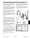
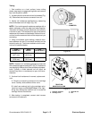
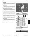
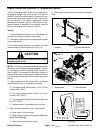
6. Check resistance of the sender with a multimeter
(Fig. 51):
A. Resistancewiththefloatin the full position should
be from 27.5 to 39.5 ohms.
B. Resistance with the float in the empty position
should be from 240 to 260 ohms.
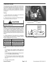
7. Replacesenderasnecessary. Install sender intofuel
tank.
8. Connect wires to fuel sender. Apply skin --over
grease (see Special Tools in this chapter) to sender ter-
minals.
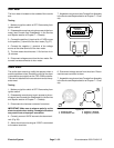
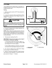
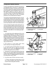
1. Fuel sender
2. White (+) lead
3. Black (--) lead
Figure 50
1
2
3
Figure 51
FULL POSITION
EMPTY POSITION
Electrical
System