


Groundsmaster 4000--D/4010--DHydraulic System Page 4 -- 70
Adjustments
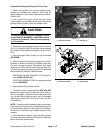
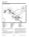
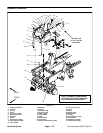
Traction Linkage Adjustment
1. Traction pedal
2. Cap screw (4 used)
3. Hex nut
4. Pedal stop
5. Washer head screw (2 used)
6. Pedal bracket
7. Lock nut (4 used)
8. Traction rod
9. Slotted roll pin
10. Lock nut
11. Flat washer
12. Compression spring
13. Spring retainer
14. Roll pin
15. Spring bracket
16. Spring shaft
17. Jam nut
18. Cap screw
19. Rod end
20. Spacer
21. Traction lever
22. Lock nut
23. Spacer
24. Flange bushing
25. Cap screw
26. Grease fitting
27. Traction pump control arm
28. Hex nut
29. Flat washer
Figure 55
FRONT
RIGHT
2
3
6
8
9
10
11
13
1
5
7
12
14
15
16
17
18
19
20
4
19
19
21
22
23
24
25
26
27
28
29
10
18
17
20
24
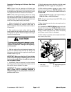
Adjustment of the traction linkage should be checked
whenever traction drive components are replaced or re-
moved.
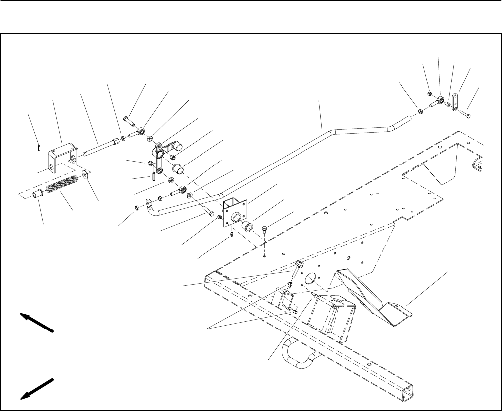
Assembly Adjustments
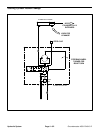
1. Traction pedal stop should be 1.500” (38 mm) above
platform bracket (item 1 in Fig. 56). If necessary, loosen
jam nuts and adjust stop location. Make sure that both
jam nuts are tightened to secure adjustment.
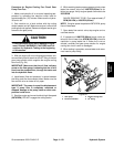
2. On traction pump end of traction rod, rod end should
be installed so that distance from end of traction rod to
center of rod end is 1.140” (29 mm) (item 3 in Fig. 56).
Tighten jam nut to secure rod end to traction rod.
3. On traction lever end of traction rod (item 4 in Fig.
56), jam nuts should position traction rod so traction
pedal remains in the neutral detent position and is at an
approximate 56
o
angle. Use a magnetic protractor to
check pedal angle.