


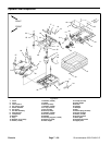
Groundsmaster 4000--D/4010--D Page 7 -- 15 Chassis
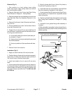
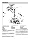
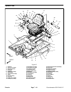
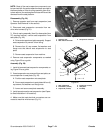
Disassembly (Fig. 13)
1. Park machine on a level surface, lower cutting units,
stop engine and engage parking brake. Remove key
from ignition switch.
2. Remove two (2) flange head screws (item 40) and
then cover plate (item 39) from outside of console arm.
Locate and retrieve two (2) spacers (item 38).
3. At front of console arm, remove screw (item 43) and
lock nut (item 7) that secure console arm covers to each
other.
4. Remove five (5) washer head screws (item 4) that
secure each cover to console arm panel.
5. Remove console arm covers from machine. As LH
cover (item 5) isremoved from consolearm, unplugwire
harness connector from headlight switch if equipped.
6. Remove electrical components from console arm as
needed using Figure 13 as a guide.
7. If necessary, remove console panel and supports
from machine using Figures 13 and 14 as guides.
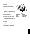
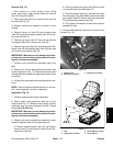
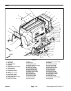
Assembly (Fig. 13)
1. Install all removed electrical and console arm com-
ponents using Figure 13 and 14 as guides.
2. Position covers to console arm. As LH cover (item 5)
is placed, plug wire harness connector to headlight
switch if equipped.
3. Secure each cover toconsole armwithfive (5) wash-
er head screws (item 4). Install screw (item 43) and lock
nut (item 7) to secure covers at front of console arm.
4. Position cover plate and spacers to outside of con-
sole arm. Secure with two (2) flange head screws.
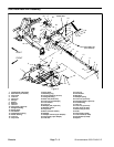
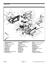
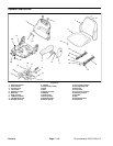
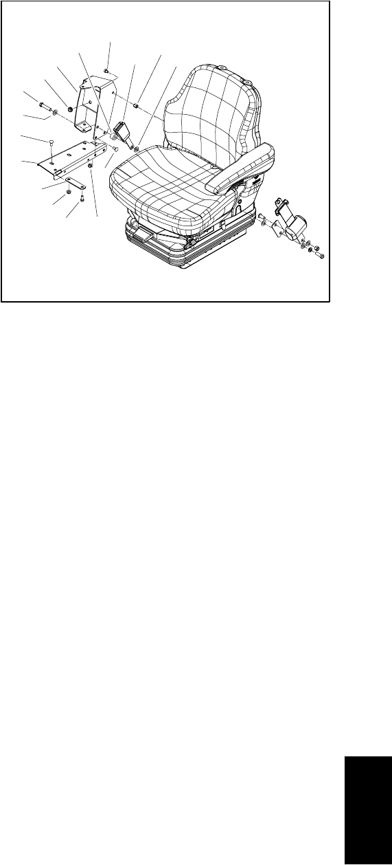
1. Flat washer
2. Seat belt buckle
3. Coupling nut
4. Spacer
5. Carriage screw (5 used)
6. Cap screw
7. Cap screw
8. Arm support
9. Grommet
10. Cap screw
11. Flange nut (5 used)
12. Support channel
13. Support bracket
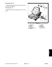
Figure 14
2
3
6
7
5
4
1
8
9
10
11
13
5
11
12
1
Chassis