


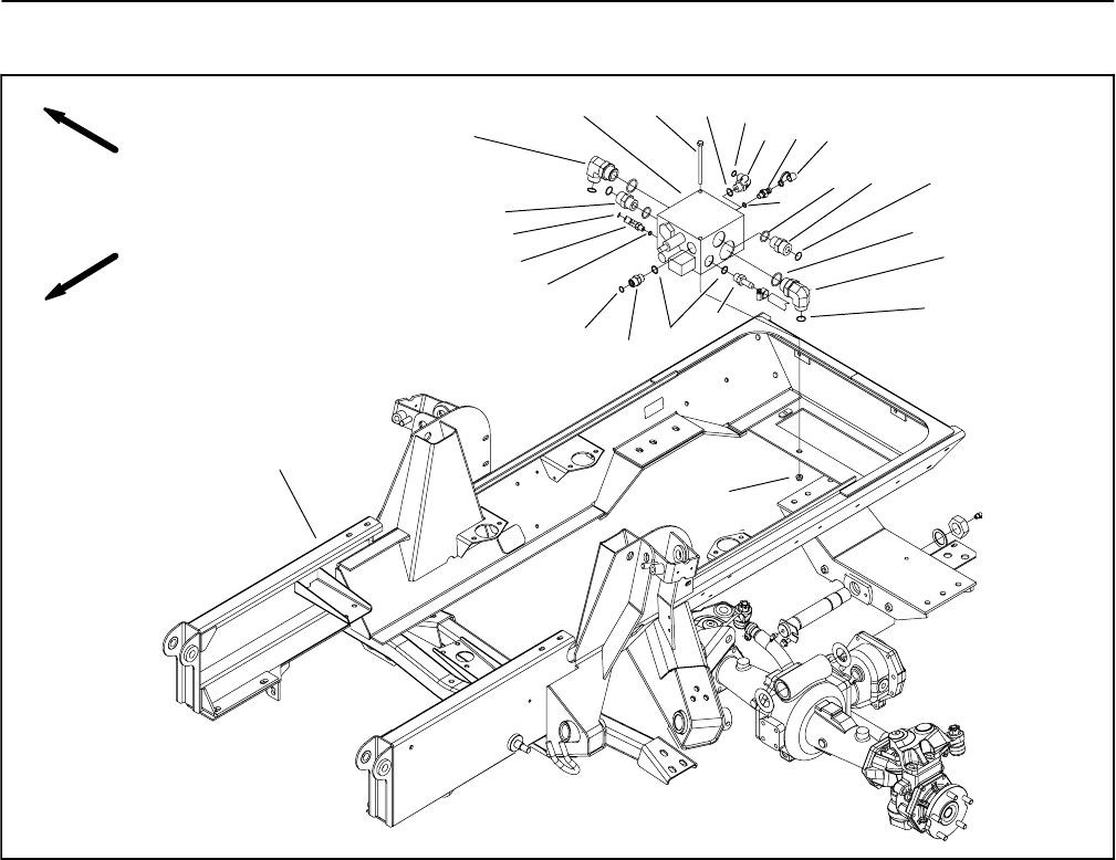
Groundsmaster 4000--D/4010--DHydraulic System Page 4 -- 96
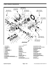
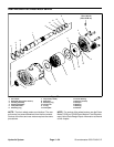
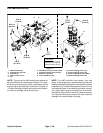
4WD Manifold
1. Frame assembly
2. 4WD manifold
3. 90
o
hydraulic fitting
4. O--ring
5. O--ring
6. Quick fitting
7. O--ring
8. Dust cap
9. Hydraulic fitting
10. O--ring
11. O--ring
12. 90
o
hydraulic fitting
13. O--ring
14. Hydraulic fitting
15. Adapter
16. Hydraulic fitting
17. O--ring
18. Cap screw (2 used)
19. Flange nut (2 used)
Figure 74
FRONT
RIGHT
1
15
16
2
18
3
14
9
12
8
6
10
10
11
7
4
5
4
5
7
17
13
12
9
19
NOTE: The ports on the 4WD manifold are marked for
easy identification of components. Example: P1 is apis-
ton pump connection port and SV is the location for the
solenoid valve (see Hydraulic Schematic in Chapter 10
-- FoldoutDrawingstoidentifythefunction of the hydrau-
lic lines and cartridge valves at each port).