


Groundsmaster 4000--D/4010--DHydraulic System Page 4 -- 102
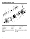
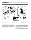
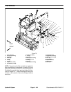
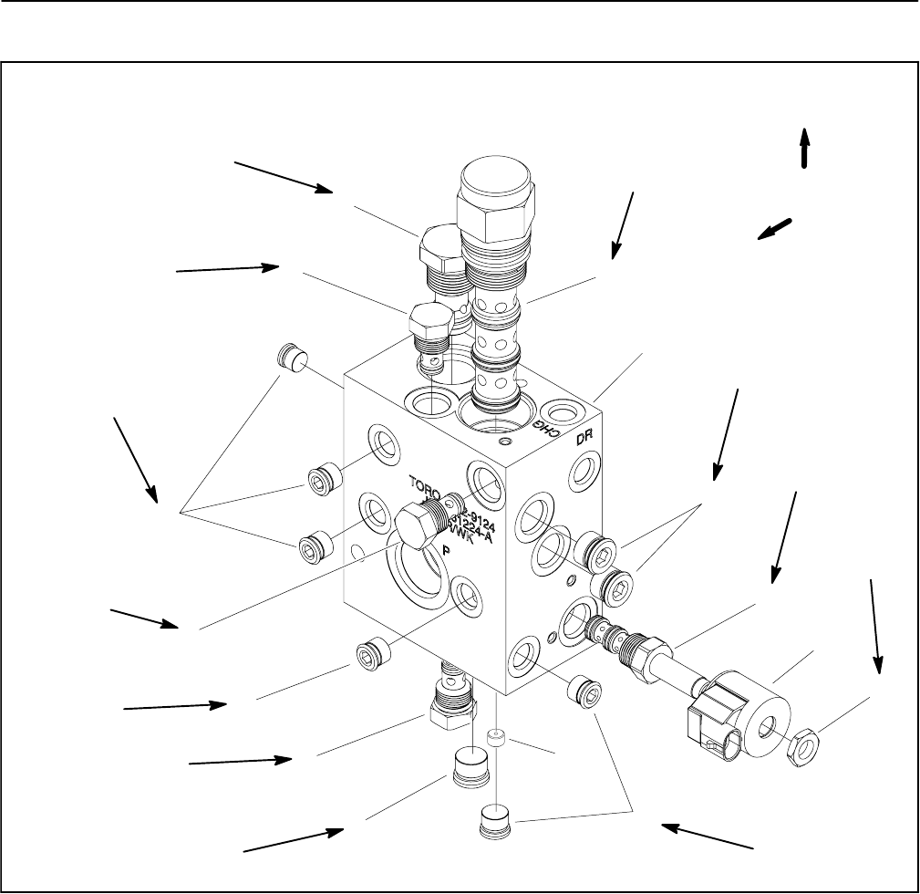
Traction (Flow Divider) Manifold Service
1. Flow divider valve
2. Pilot directional valve
3. Orifice (0.020)
4. Traction manifold
5. Check valve
6. SAE #8 plug with O--ring
7. Solenoid coil
8. Nut
9. Solenoid cartridge valve
10. SAE #6 plug with O--ring
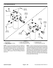
Figure 77
7
9
1
2
3
4
8
6
5
10
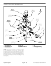
50 ft--lb
(67 N--m)
198 in--lb
(22.4 N--m)
5
5
10
10
6
5 ft--lb
(6.7 N--m)
20 ft--lb
(27 N--m)
40 ft--lb
(54 N--m)
40 ft--lb
(54 N--m)
20 ft--lb
(27 N--m)
20 ft--lb
(27 N--m)
20 ft--lb
(27 N--m)
50 ft--lb
(67 N--m)
198 in--lb
(22.4 N--m)
198 in--lb
(22.4 N--m)
FRONT
UP
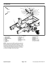
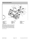
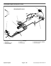
NOTE: The ports on the traction manifold are marked
for easy identification of components. Example: P2 is
the gear pump connection port and CD is theconnection
for the case drain from the deck motors (see Hydraulic
Schematic in Chapter 10 -- Foldout Drawings to identify
the function of the hydraulic lines and cartridge valves
at each port).