


Groundsmaster 4010--D Operator CabPage 9 -- 11
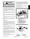
CAUTION
The air conditioning system is under high pres-
sure. Do not loosen any system fitting or compo-
nent until after the system has been completely
discharged by a certified A/C service technician.
5. Have refrigerant evacuated from air conditioning
system by a certified A/C service technician.
6. Label and remove hoses from heater core, evapora-
tor and drier--receiver. Immediately cap hoses and fit-
tings to prevent moisture and contaminants from
entering the system.
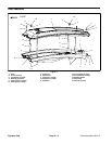
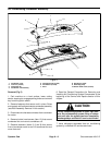
7. Loosen hose clamp that secures air duct hose to
heater/evaporator assembly covers. Slide hose from
covers.
8. Remove screws thatsecure top coverto bottom c ov-
er. Remove top cover to access heater/evaporator as-
sembly.
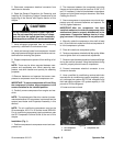
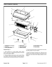
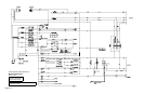
9. Disassembleheater/evaporatorassembly using Fig.
9 as a guide.
NOTE: Thereplacement of the drier--receiver is recom-
mended whenever the air conditioning system is
opened.
Installation (Fig. 7)
1. Assemble heater/evaporator assembly using Fig. 9
as a guide. Make sure that expansion v alve is covered
with insulating tape to prevent condensation issues.
2. Position heater/evaporator assembly into bottom
cover in headliner. Secure top cover to bottom cover
with removed screws.
3. Slide air duct hose ontoheater/evaporator assembly
covers and secure with hose c lamp.
4. Remove caps that were placed on hoses and fittings
during the removal process. Using labels placed during
removal, properly secure hoses to heater core, evapo-
rator and drier--receiver.
5. Make sure that condensation hoses are secured to
bottom housing of heater/evaporator assembly and are
routed to cab frame for proper draining of condensate.
6. Connect wire harness connectors to fan motor and
binary switch on drier--receiver.
7. Make sure that all machine air conditioning compo-
nents are installed and secure.
8. Have a certified air conditioning service technician
evacuate the air conditioning system completely, prop-
erly recharge the system with R134a refrigerant and
then leak test the system. A/C system capacity is 1.25
pounds of R134a refrigerant.
9. Operate the heater system to make sure that no en-
gine coolant leaks exist.
10.Lower and secure roof assembly (see Roof Assem-
bly Installation in this section).
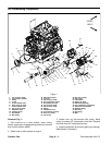
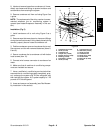
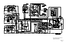
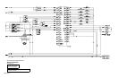
1. Heater/evaporator assembly
2. Heater valve
3. A/C hose: evaporator to compressor
4. Air duct hose
5. A/C hose: compressor to condenser
6. A/C hose: condenser to drier
7. Heater hose: thermostat to heater valve
8. Heater hose: heater core to water pump
9. Heater hose: heater valve to heater core
10. Condensation drain hose (2 used)
11. A/C hose: drier to evaporator
Figure 8
2
1
3
4
7
8
6
5
9
10
11
10
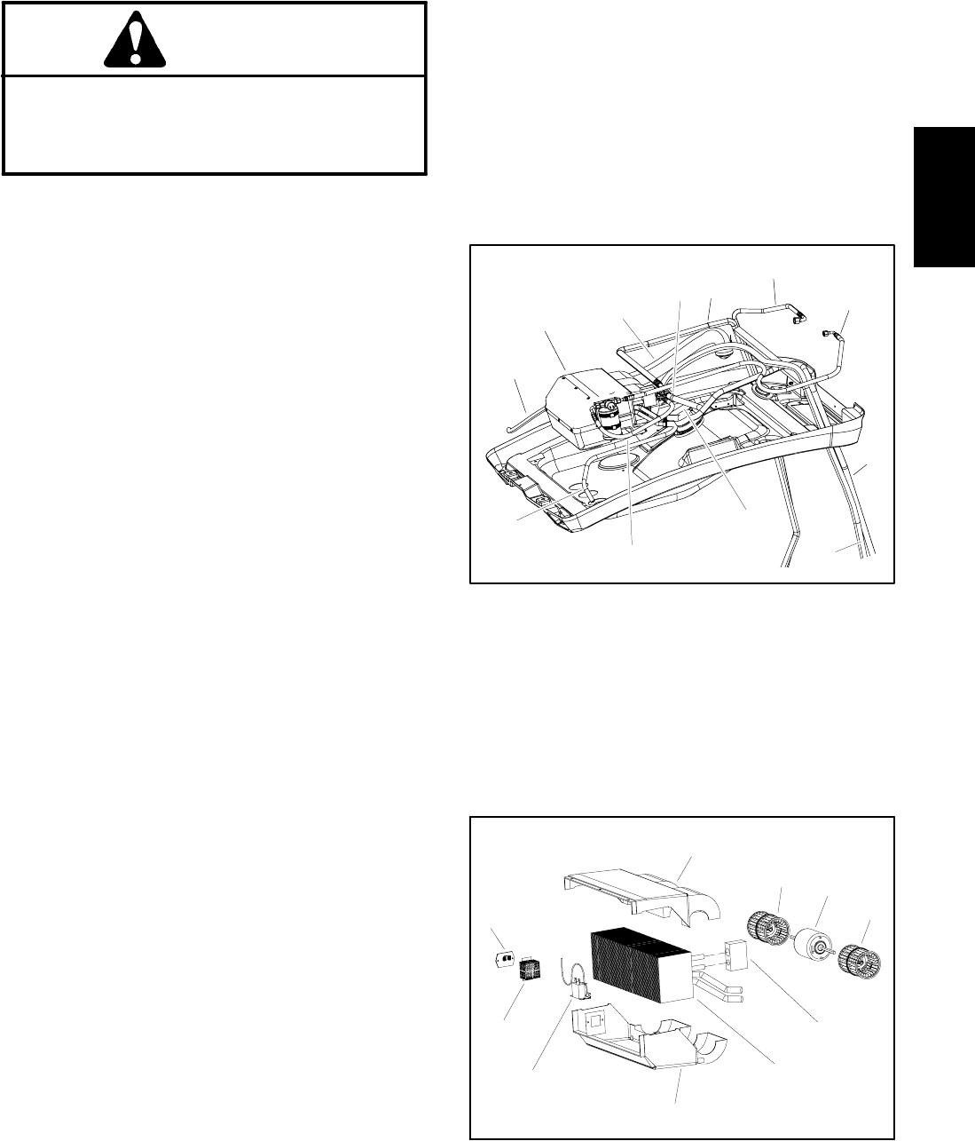
1. Fan motor
2. Blower wheel
3. Heater/evaporator core
4. Expansion valve
5. Freeze switch
6. Resistor guard
7. Bottom housing
8. Top housing
9. Resistor
Figure 9
2
1
3
4
7
8
6
5
9
2
Operator
Cab