


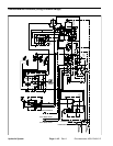
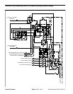

Groundsmaster 4000--D/4010--D Hydraulic SystemPage 4 -- 41
Procedure for Traction Circuit Relief Pressure Test
1. Make sure hydraulic oil is at normal operating tem-
perature by operating the machine under load for
approximately ten (10) minutes. Make sure the hydrau-
lic tank is full.
Move machine to anopen a rea, awayfrompeople
and obstructions.
CAUTION
2. Drive machine to an open area, lower cutting decks,
turn the engine off and apply the parking brake.
CAUTION
Prevent personal injury and/or damage to equip-
ment. Read all WARNINGS, CAUTIONS and Pre-
cautions for Hydraulic Testing at the beginning
of this section.
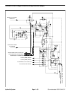
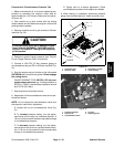
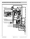
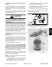
3. Connect a 10,000 PSI (700 bar) pressure gauge to
traction circuit test port for function to be checked (Fig.
27 or 28).
4. Start the engine and move throttle to high idle speed
(2870 RPM). Release parking brake. Make sure that Hi/
Low speed switch is in the Hi speed (2WD) position.
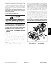
5. Sit on seat,apply brakes fully and slowly depress the
traction pedalin the appropriate direction (forward or re-
verse). While pushing traction pedal, look at pressure
reading on gauge:
GAUGE READING TO BE:
Forward: 3750 to 4250 PSI (259 bar to 293 bar)
Reverse: 4750 to 5250 PSI (328 to 362 bar)
6. Release traction pedal and stop engine. Record test
results.
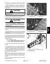
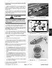
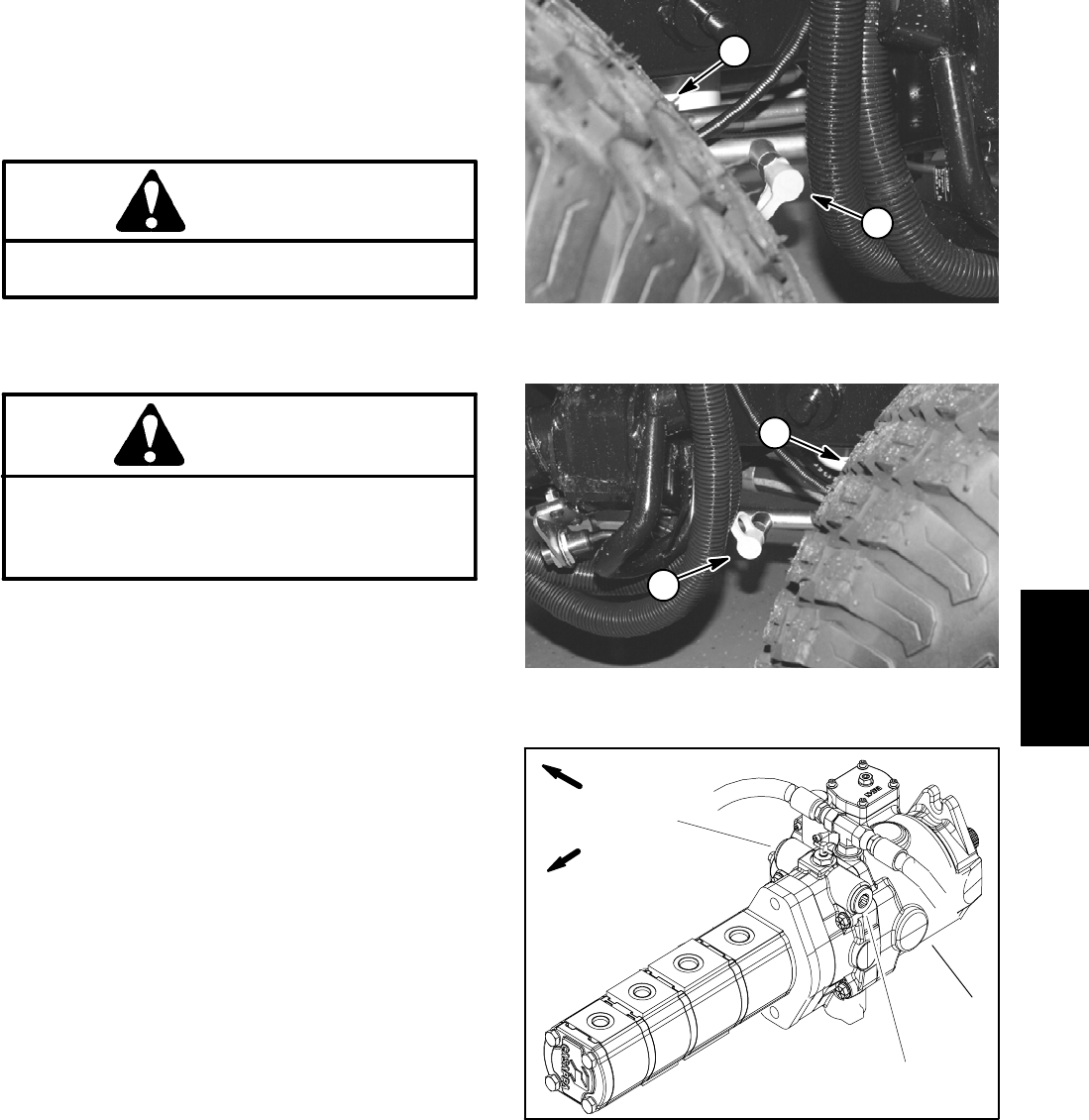
7. If traction pressure is too low, inspect traction pump
relief valves (Fig. 29). C lean or replace relief valves as
necessary. These cartridge type valves are factory set,
and are not adjustable. If relief valves are in good condi-
tion, traction pump or wheel motors should be sus-
pected of wear and inefficiency.
NOTE: Seal leakage across pilot directional valves
PD1 and PD2 in 4WD manifold can cause low forward
traction pressure withreverse pressure meetings pecifi-
cations.
8. When testing is completed, disconnect pressure
gauge from test port.
1. Forward traction port 2. Left front wheel
Figure 27
1
2
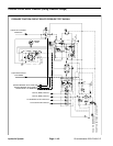
1. Reverse traction port 2. Right front wheel
Figure 28
1
2
1. Forward relief valve
2. Reverse relief valve
3. Traction pump
Figure 29
1
2
3
FRONT
RIGHT
Hydraulic
System